
In the first part of this guide, it has been shown how to start an WiFi access point and a TCP server with an RYWB116 module (RYWB116_Lite breakout board). Initially, I planned to explain in the second part how to use an RYWB116_Lite breakout board in combination with an Arduino microcontroller. Unfortunately, after playing around some time with the RYWB116_Lite, I got an error message (“invalid firmware”) indicating that the firmware got damaged. While I tried to “re-burn” a new firmware to the module, I found very little information on how to do this. Therefore, I decided to change the topic of this second part to “how to update/upgrade the firmware of the RYWB116 module”.
Additional remark, if your module does also not work anymore and you are looking for a solution: I was not able to revive my module by updating the firmware :(
Hardware/Software Requirements
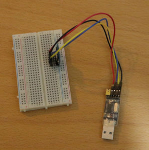
In order to upgrade the firmware, you have to connect the RYWB116_Lite module to a PC/notebook. My previous tutorial explains how to build up such a connection by utilizing a USB-to-TTL adapter.
Equipment:
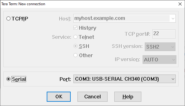
Terminal Software Tera Term
In my previous tutorial, I recommended to use HTerm to send commands to the module. Unfortunately, at least to my knowlegde — HTerm does not support to transfer data via the Kermit protocol which is required to upgrade the firmware.
As an alternative, I recommend to use Tera Term that is btw. especially popular in Japan. In contrast to HTerm, it does not offer that many convenience functions, such as the predefined command list. But still, it is a very solid & robust terminal program. As mentioned before, the Kermit protocol has to be supported which is fulfilled by Tera Term. Kermit is a file transfer protocol which came up in the 80s. It is still used for transferring data for serial connections.
Firmware
Downloadable firmware versions can be found on Redpine website: https://www.redpinesignals.com/. As mentioned in the previous article, the module is based on Redpine’s RS9116 technology.
Procedure
- Start Tera Term and connect to the RYWB116_Lite by using the COM port of the USB connection to the USB-to-TTL adapter.
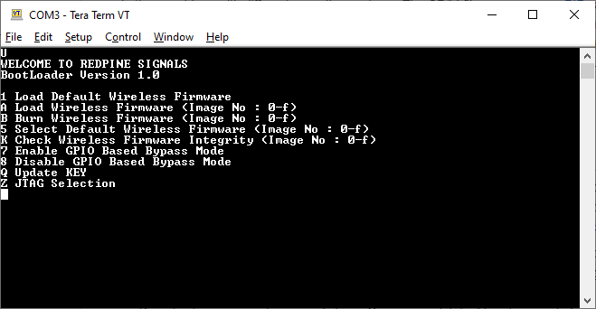
- Next, when the connection is started, enter “?”. The module will respond with “U”.
- Enter “U”. The module will show the boot menu:
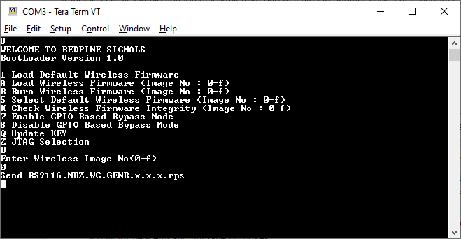
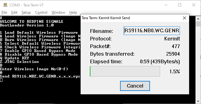
- Then enter “B” to select burning a new firmware to the module. The module will ask you which firmware image should be used.
- Enter “0” to select the image firmware slot. The module asks you to send the new firmware (via the kermit protocol).
- Go to “File” -> “Transfer” -> “Kermit” -> “Send…”. A file dialog opens up. Please select the firmware file (.rps) that you want to send to the module. You can get an .rps file from Redpine’s support. Tera Term will send the selected file:
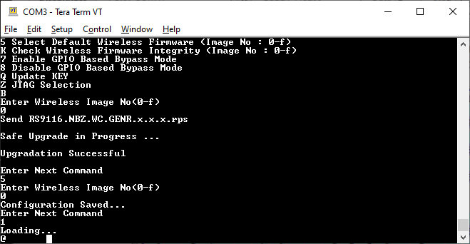
- The module will check whether the firmware is valid. If you downloaded the wrong file from the Redpine website etc., the module will recognize the invalid file.
- When finished, the module will ask you what to do next. Select “5” and then “0” to select the default firmware image:
In my case, a new firmware did not make the module boot up again. I looked a bit deeper into the topic but was not able to fully identify the source of the problem. My guess is that the module is simply broken or permanently damaged.
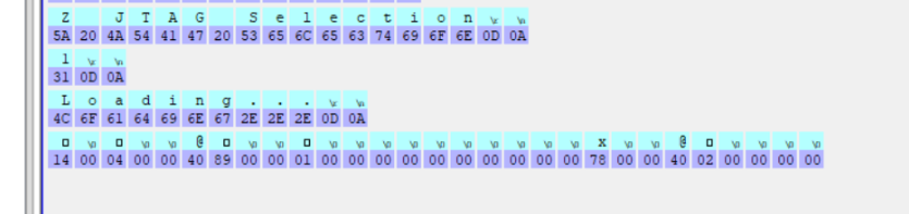
With the new firmware, I get some weird characters starting with an “@” character after loading the firmware. The detailed byte sequence is: 0x14 0x00 0x04 0x00 0x00 0x40 0x89 0x00 0x00 0x01 0x00 0x00 0x00 0x00 0x00 0x00 0x00 0x00 0x00 0x00 0x78 0x00 0x00 0x40 0x02 0x00 0x00 0x00 0x00
If you got the same sequence and were able to solve it, I would be glad if you could share your solution in the comments.
Btw.: More information on the Reyax RYWB116_Lite can be found here: http://reyax.com/products/rywb116_lite/ (Specs, datahseet, etc.)
Hi, I noticed elsewhere that you had a posting on modifying wires for electronics. I wonder if you have a suggestion for this problem: When I use my preferred TFT shield on Arduino Due, the SPI pins are not accessible for connection to my SD. The connectors for jumper wires are too large to fit under the TFT shield. Shorter connectors, possibly t-shaped could solve the problem if they existed. I haven’t had success in trying to solve the problem with software (reassigning the SPI MOSI, MISO and SCK) on the Due.
Would appreciate your thoughts.
Thanks,
Mike
beachbum975@gmail.com
Hi, I got the same problem after upgrade firmware, and i found this problem is “Entering Binary Mode”, because the ‘@’ after Loaing …………
If you need exit the binary mode, you need send ‘0x55’ again after ‘0x1C'(set auto baudrate).
================================================================
reset -> ‘0x1C'(auto baudrate) -> ‘0x55′(confirm) -> ‘0x55′(exit binary mode) -> ‘0x31′(default firmware select) ->….