
This tutorials shows how to wire the RYB080I bluetooth module to an Arduino Uno. Moreover, an OLED SH1106 mini display is wired to the Arduino. The idea is that messages are received via bluetooth and then displayed on the OLED display. The messages are sent from an ‘bluetooth serial terminal’ smartphone app.
Equipment:
| Reyax RYB080I | |
| OLED display SH1106 | |
| Arduino Uno | |
| Jumper Wires | |
| 5V-to-3.3V converter | |
| USB-to-TTL adapter (for playing around with the module) |
Reyax RYB080I
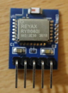
The RYB080I is a Bluetooth v4.2 + v5.0 BLE module. It comes with a TI CC2640R2F ARM® Cortex®-M3 chip and has a PCB-integrated antenna. The module can be controlled by just sending so-called AT commands. The AT commends are used, e.g. to check the connection status, set the power mode, scan bluetooth devices etc.
My module comes on a ready-to-use breakout board called RYB080I_lite. Fortunately, the module is fully set up for bluetooth connections when starting it for the first time. In my opinion, this is an advantage especially for ‘makers’. The breakout board has five pins for powering and communicating with the module. The following table shows which pins are available including their purpose.
| Pin Name | Input/Output | Description |
|---|---|---|
| GND | Input | Ground. |
| RST | Input | Low reset reset signal. |
| TXD | Output | UART serial output. |
| RXD | Input | UART serial input. |
| VDD | – | Input supply voltage (1.8-3.8V). |
Part I: Playing around with the Reyax RYB080I module
Before, we start with wiring the module to an Arduino Uno, we do some prototyping with the RYB080I module. In order to do this, we require a USB-to-TTL adapter and a terminal program.
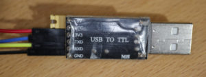
USB-to-TTL adapters enable to build up serial connection from a PC/notebook to modules offering an TXD (transmit) and RXD (receive) pin. Typically, these adapters can also power the modules with 3.3V or 5V. Simply plug the adapter into an USB port of your computer. To wire an adapter to the RYB080I module, you can use (female/female) jumper wires. The following table shows how to wire the USB-to-TTL adapter to the RYB080I module. Notice: The adapter must power the module with 3.3V (instead of 5V) to avoid damaging the module due to high voltages.
| USB-to-TTL Pin | RYWB116_Lite Pin |
|---|---|
| 5V | no connection / yellow jumper with USB-TO-TTL VCC |
| VCC | no connection / yellow jumper with USB-TO-TTL 5V |
| 3V3 | VDD |
| TXD | RXD |
| RXD | TXD |
| GND | GND |
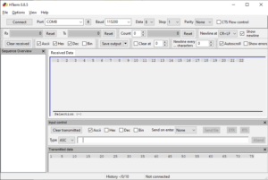
Besides wiring the adapter, we require a “terminal program” on our computer to send commands to the module. In this tutorial, I make use of HTerm which is a free-to-use terminal program. It has many convenience functions which makes it very comfortable when working with serial connections. I won’t introduce HTerm in this tutorial, since we require only some basic functions.
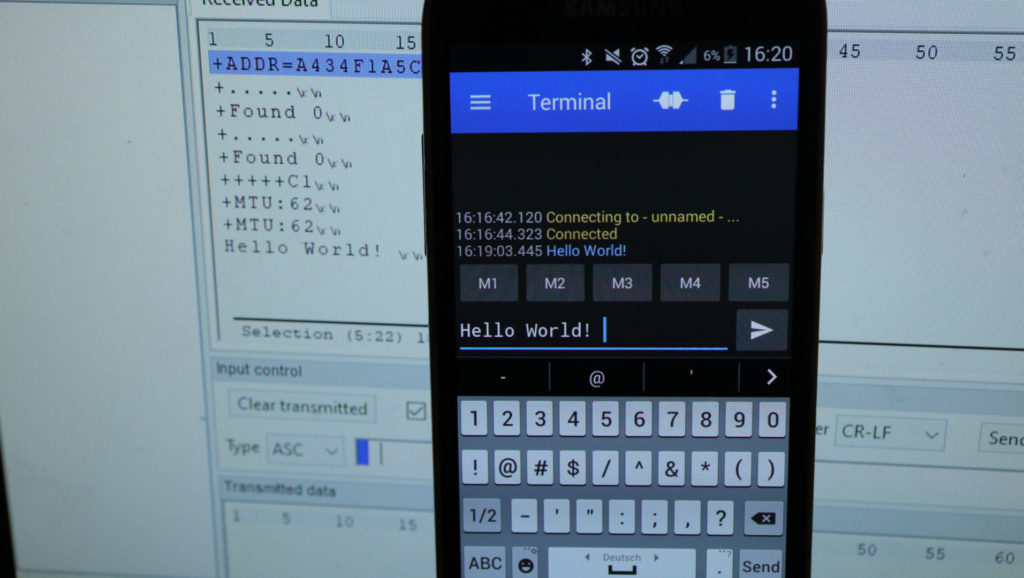
Now, we are fully set to play around a little bit with the RYB080I module. First, we use HTerm to connect to the adapter/module (Baud: 9600, Data 8, Stop 1, Parity None). When sending commands, it is important to end each line with the CR+LF characters. You find a full list of commands in the data sheet. As a start, you can send the “AT” command to test whether the module is able to receive commands. If the module received the command, it will respond with “+OK”:
< AT\r\n
> +OK\r\n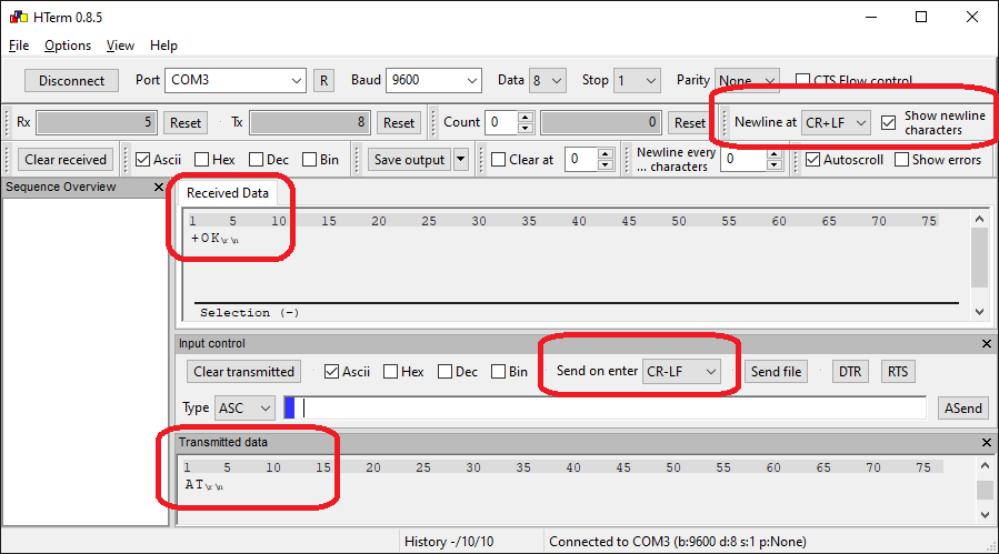
Btw. sometimes the module does not react to a sent command, even if wired correctly. Just resend the command a few times. Normally, after 2-3 tries, it should send a response. Ok, let’s ask the module about its MAC address by sending the “AT+ADDR?” command. As a response, you should receive the modules MAC address (attention: the MAC address of you module will be different from mine!):
< AT+ADDR?\r\n
> +ADDR=A434F1A5C026\r\n
Next, use a smartphone app to connect to the RYB080I and send some messages. If we stay connected in HTerm, we will see the message that are transmitted via bluetooth. The module is already fully set up to start bluetooth connections. There exist multiple apps that can start bluetooth connections with the module. Since I have an Android phone, I used Serial Bluetooth Terminal which is free-to-use. The app is simple to use, just go to devices and look for “REYAX_BLE_RYB080I” (default bluetooth boradcast name of the module). If you touch the name, you get connected to the module. In my setup, it was required to use a custom bluetooth LE profile (the app gives you some guidance). When you established the connection, you can send messages from the app to the module. If performed successfully, the bluetooth message will appear in HTerm:
If you completed all steps, you are well prepared for the next step. We use the same mechanism to send messages from the app to the bluetooth module. An Arduino Uno, connected to the module, will show the message on an OLED display.
Part II: Displaying bluetooth message on an OLED display (by utilizing an Arduino Uno)
Wiring
First, we have to do all the wiring: The RYB080I bluetooth module and OLE display have to be wired to the Arduino. The next table shows how the bluetooth module is wired to the Arduino. Important: The bluetooth module’s RXD pin expects a voltage level of 3.3V (instead of Arduino’s 5V level). As a consequence, the Arduino’s digital pin 3 should not directly be wired to the RYB080I’s RXD pin. In such cases, I make use of so-called 5V-to-3.3V converters (come with many names).
| RYB080I Pin Name | WIRE COLOR | ARDUINO PIN NAME |
|---|---|---|
| GND | black | GND |
| RST | – | – (not used) |
| TXD | blue | 2 |
| RXD | yellow (via 5V-to-3.3V converter module!) | 3 |
| VDD | orange | 3.3V |
Then, the OLED display has to be wired to the Arduino which is not that simply. So far, I made many tutorials in which a display is used, e.g. the tutorial about the KMR 1.8 display. I receive a lot of messages from readers that my code does not work with their setup. Typically, it turns out that they do not use the exact same display type that I’m using. Please keep this in mind, when using my wiring and source code for your project. The display that I’m using in this tutorial is a noname 1.3″ OLED 4-SPI module with seven pins. The following table shows how to wire the display to the Arduino:
| 1.3″ OLED 4-SPI Pin Name | WIRE COLOR | ARDUINO PIN NAME |
|---|---|---|
| GND | black | GND |
| VDD | red | 5V |
| SCK | yellow | 13 |
| SDA | blue | 11 |
| RES | white | 8 |
| DC | green | 9 |
| CS | grey | 10 |
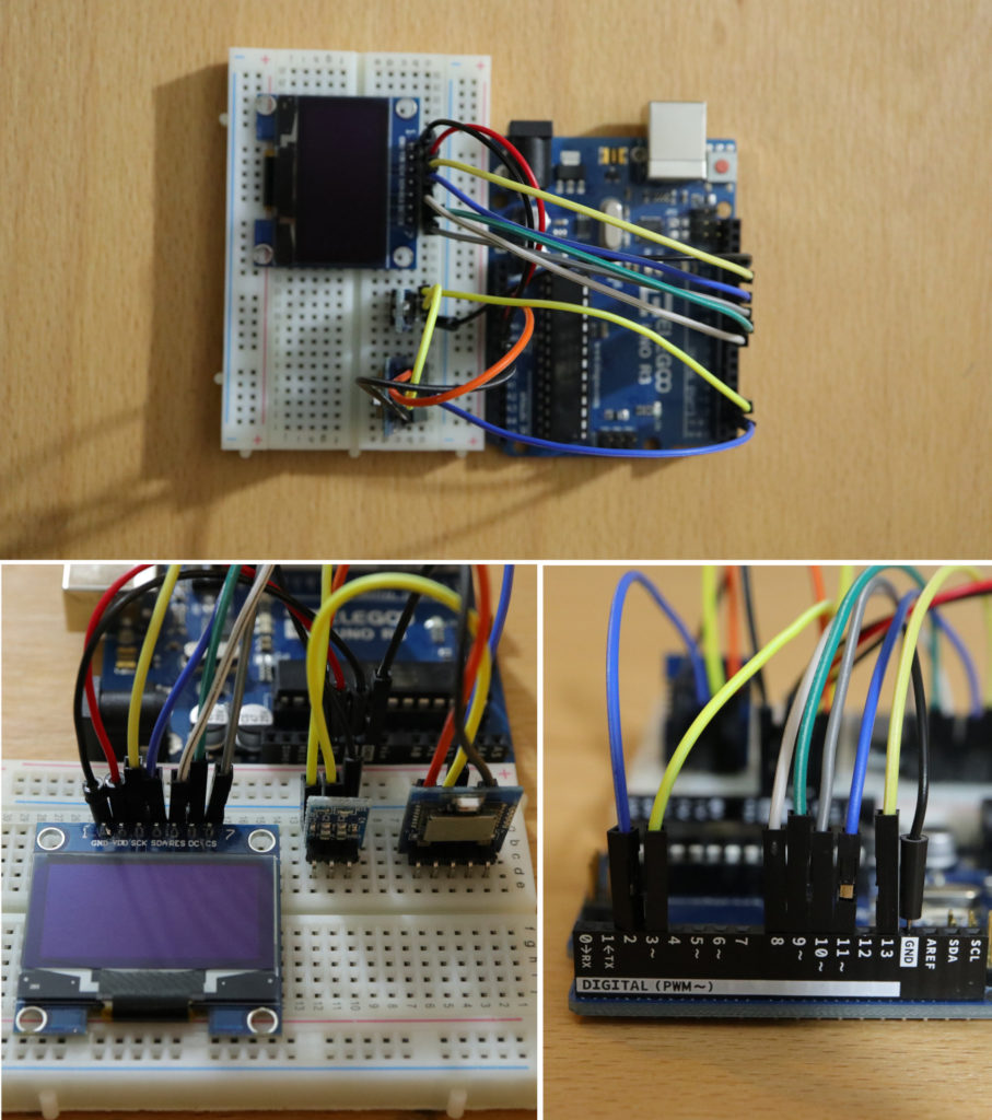
If everything has been wired correctly, your setup should look like this:
Software / Source code
The source code makes use of the software serial and the 8g2 library. The software serial library is utilized to read all the messages coming from the bluetooth module. The 8g2 library is a library for controlling displays that supports tons of different display types. Luckily, also my display type was supported (U8X8_SH1106_128X64_WINSTAR_4W_SW_SPI).
When the Arduino program starts, the display and software serial is initialized. When done, the display shows the message “I’m ready”. In the Arduino’s loop function, characters are read from the software serial (bluetooth module) and stored to a string buffer. If a line ending (‘\n’) is received, the content of the string buffer is shown on the display.
/*
MIT License
Copyright 2020 Michael Schoeffler (https://www.mschoeffler.de)
Permission is hereby granted, free of charge, to any person obtaining a copy of this software and associated documentation files (the "Software"), to deal in the Software without restriction, including without limitation the rights to use, copy, modify, merge, publish, distribute, sublicense, and/or sell copies of the Software, and to permit persons to whom the Software is furnished to do so, subject to the following conditions:
The above copyright notice and this permission notice shall be included in all copies or substantial portions of the Software.
THE SOFTWARE IS PROVIDED "AS IS", WITHOUT WARRANTY OF ANY KIND, EXPRESS OR IMPLIED, INCLUDING BUT NOT LIMITED TO THE WARRANTIES OF MERCHANTABILITY, FITNESS FOR A PARTICULAR PURPOSE AND NONINFRINGEMENT. IN NO EVENT SHALL THE AUTHORS OR COPYRIGHT HOLDERS BE LIABLE FOR ANY CLAIM, DAMAGES OR OTHER LIABILITY, WHETHER IN AN ACTION OF CONTRACT, TORT OR OTHERWISE, ARISING FROM, OUT OF OR IN CONNECTION WITH THE SOFTWARE OR THE USE OR OTHER DEALINGS IN THE SOFTWARE.
*/
/*
* This is example code of an tutorial about how to use the RYB080I bluetooth module in combination with an OLED display module.
* Messages that are received by the bluetooth module are shown on the display module.
*/
#include <U8x8lib.h>
#include <SoftwareSerial.h>
// OLED PINs
#define OLED_SCK 13
#define OLED_MOSI 11
#define OLED_CS 10
#define OLED_DC 9
#define OLED_RES 8
// Bluetooth module pins
#define BLE_RX 2
#define BLE_TX 3
U8X8_SH1106_128X64_WINSTAR_4W_SW_SPI display (OLED_SCK, OLED_MOSI, OLED_CS, OLED_DC, OLED_RES); // display
SoftwareSerial sserial = SoftwareSerial(BLE_RX, BLE_TX); // bluetooth module serial connection
String data; // variable used as buffer for the serial connection
void setup() {
display.begin(); // Display is now ready to use
display.setFont(u8x8_font_chroma48medium8_r); // set font type
display.clear(); // clear contents of display, set cursor to 0,0
sserial.begin(9600); // start serial connection to bluetooth module
display.print("I'm ready!"); // Show message on display
}
void loop() {
while(sserial.available()) {
char c = sserial.read(); //gets one byte from serial buffer (bluetooth module)
if (c != -1) {
data += c; // store character into buffer string
if (c == '\n') { // end of line detected
display.clear(); // clear display
display.print(data); // show new message on display
data = ""; // clear buffer string
break;
}
}
}
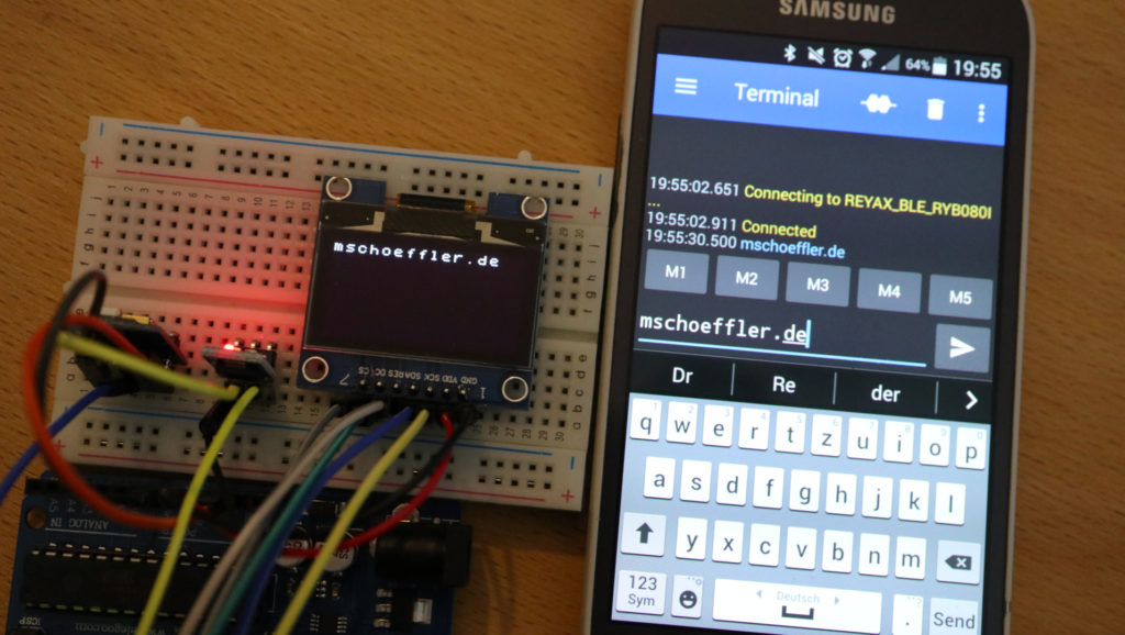
}If you executed everything correctly, you should be able to send messages from the smartphone app to the module. At the same time, the messages should appear on the OLED display:
Video tutorial
![[Tutorial] Bluetooth Messaging from Smartphone to Arduino-controlled Display | RYB080I + SH1106](https://mschoeffler.com/wp-content/plugins/wp-youtube-lyte/lyteCache.php?origThumbUrl=https%3A%2F%2Fi.ytimg.com%2Fvi%2Fj07Dun7QnYo%2F0.jpg)
[…] this tutorial, I use the terminal HTerm. I already covered some aspects of HTerm in a previous tutorial, why I won’t introduce it here […]
[…] to have a look in some module settings. As in my other tutorials about Reyax modules ( RYWB116, RYBI080, and RYS8830), a “USB-to-TTL” device is used to establish a connection between a PC and […]
Ant it wont turn on unless you trigger it awake with the reset pin, so if you do not mention that pin “nothing in here would work!
Is it possible to use GATT with this chip? The datasheet says that you can, although there don’t appear to be any commands to get a list of attributes.