Passive infrared (PIR) sensors measure infrared (IR) light emitted from objects that are in their field of view. PIR sensors enable to detect movement by change in IR light. They are considered as “passive”, since PIR sensors do not actively emit any IR light. Typically, PIR sensors are used for automatic house lighting installations (indoor and outdoor) or security installations.
The HC-SR501 sensor is an easy-to-use PIR sensor that can be used with an Arduino microcontroller. In contrast to the (more simple) HC-SR505 sensor, the HC-SR501 allows to adjust its sensitivity and signal time-delay. This tutorial shows how to use the HC-SR501 PIR sensor with an Arduino Uno for a very simple example application.
Related products
HC-SR501 PIR Sensor for Movement Detection
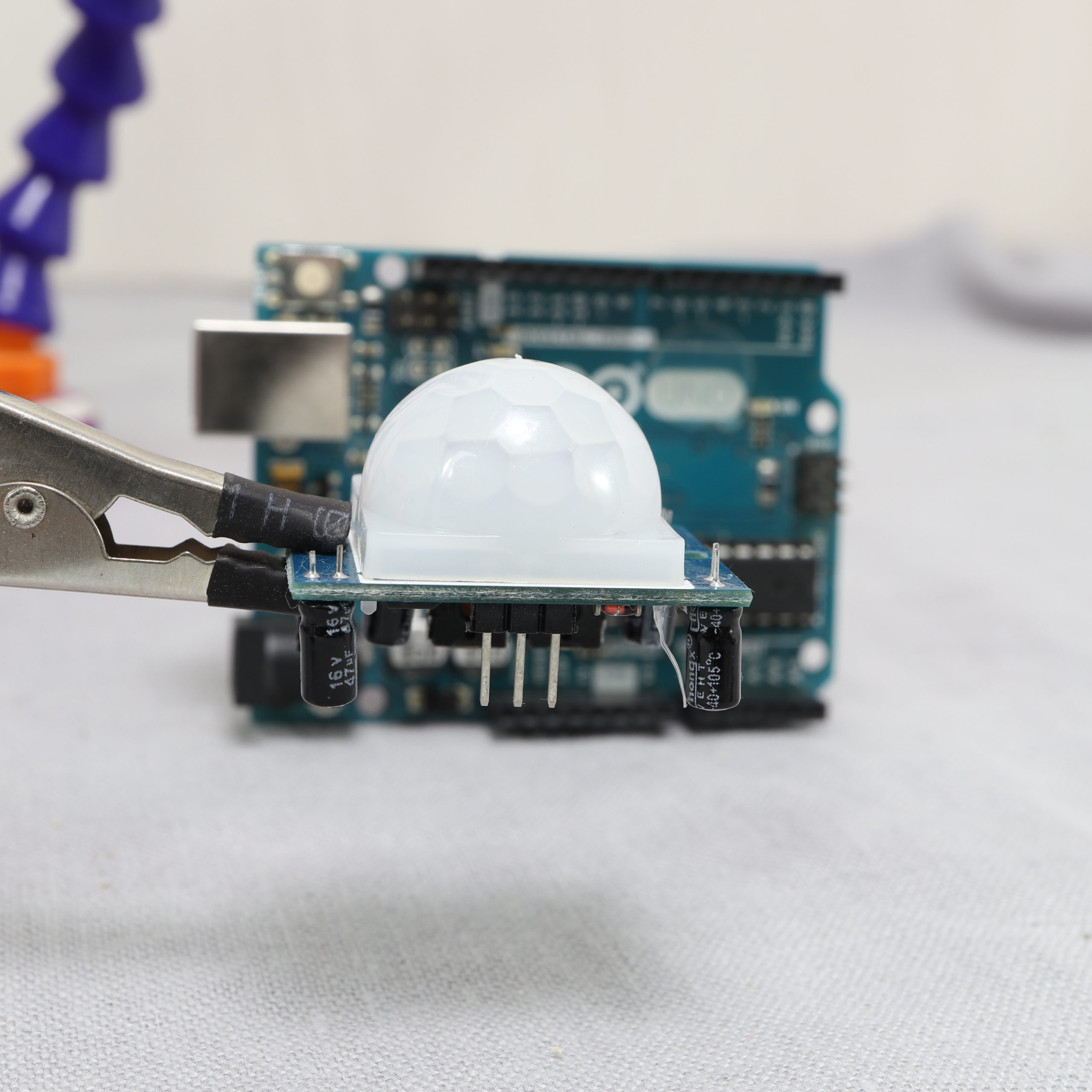
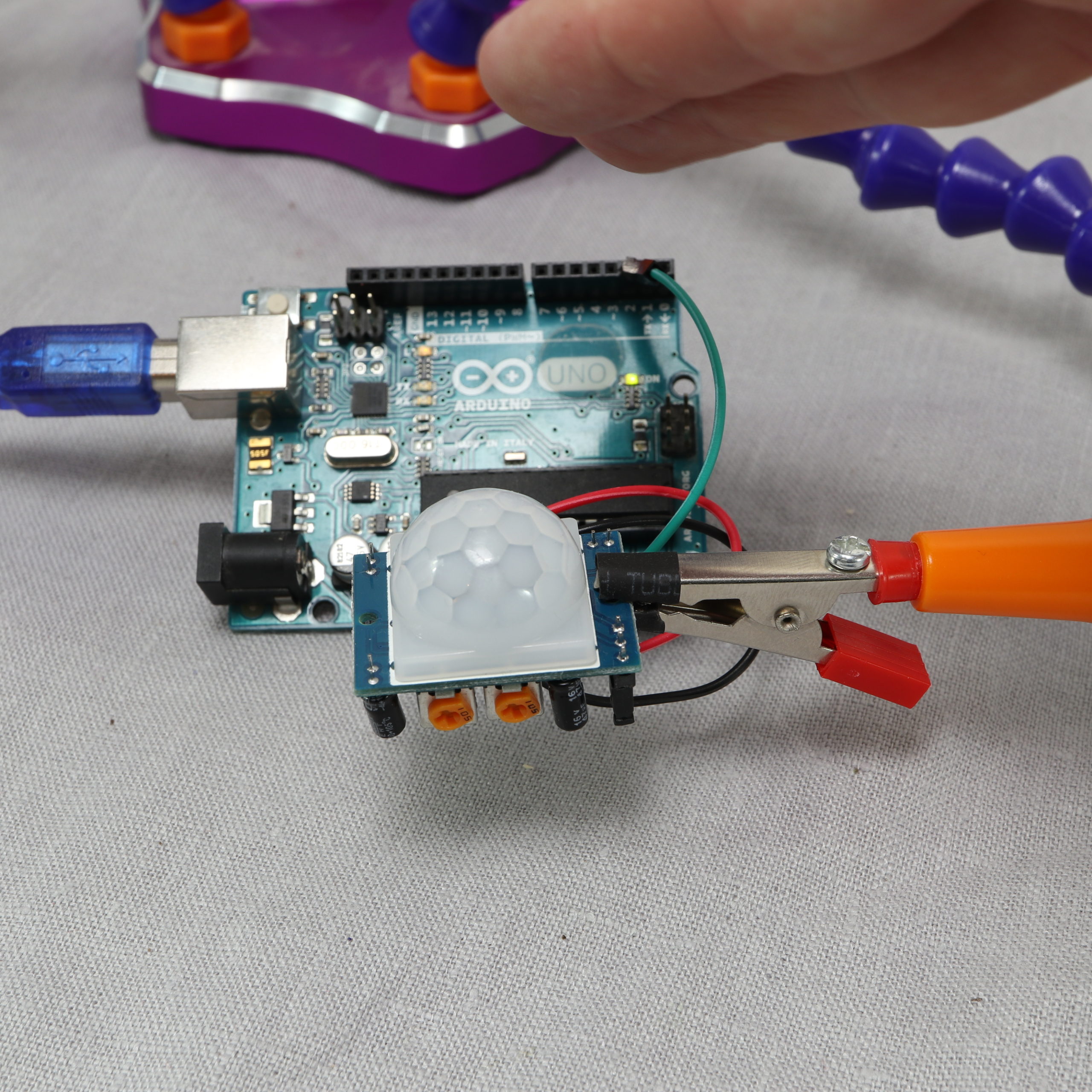
The HC-SR501 PIR sensor comes as breakout board with the PIR sensor on top. The PIR sensor has a “fresnel lens”-shaped cover to protect the sensor and to have a sensing angle of about 110°.
The breakout board has two potentiometers to adjust the sensitivity and time-delay. The higher the sensitivity, the lower the required change in IR light to detect movement. If the PIR sensor does not trigger when something moves, just increase the sensitivity. Moreover, the sensitivity influences also the sensing range. Rotating it counterclockwise decreases the sensitivity (to a minimum of about 3m). Rotating the potentiometer clockwise increases the sensitivity (to a maximum of about 7m).
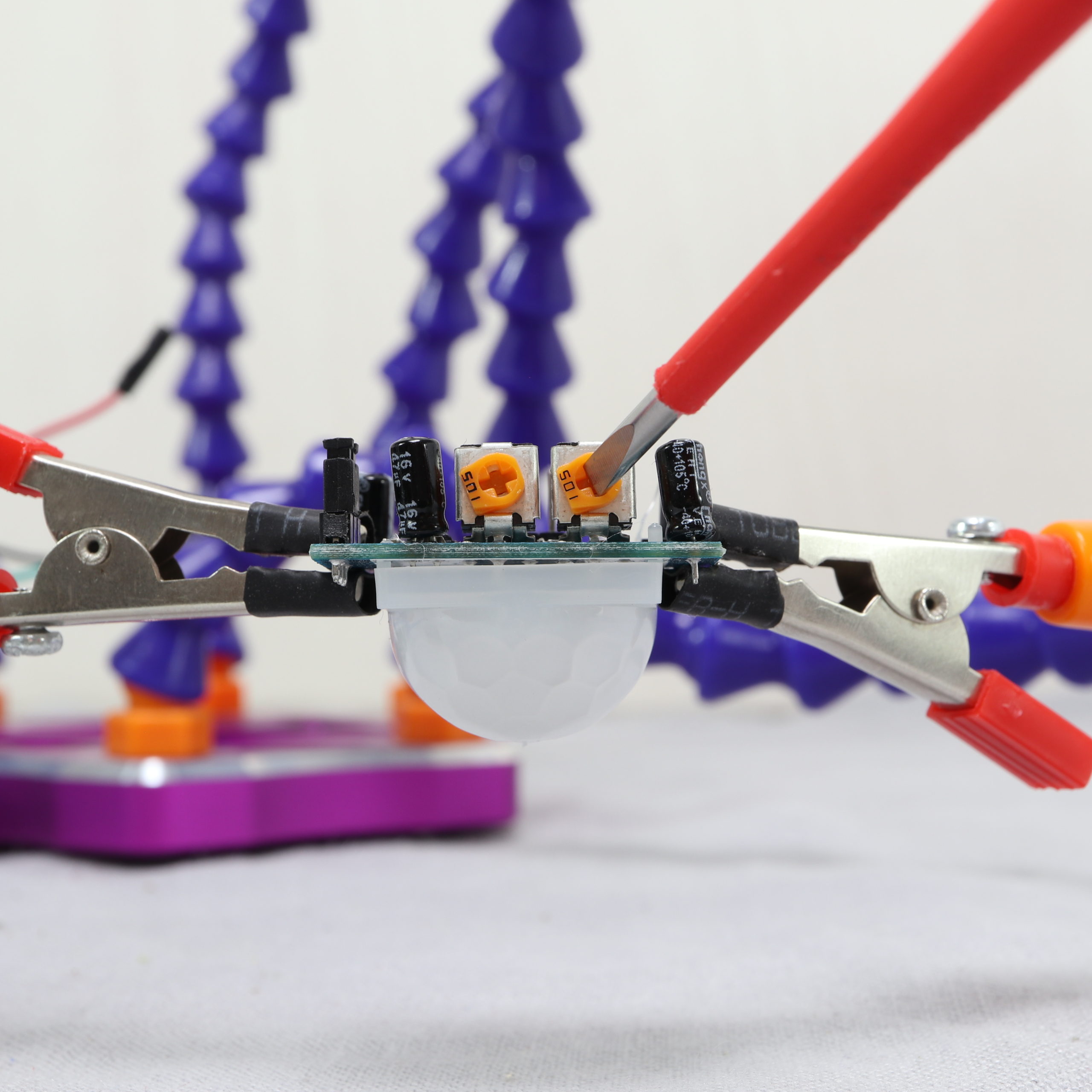
The time-delay sets how long the output pin remains “high” after motion is detected. The time-delay ranges from 3 seconds to 300 seconds (5 minutes). The time-delay can be increased by turning the potentiometer clockwise.
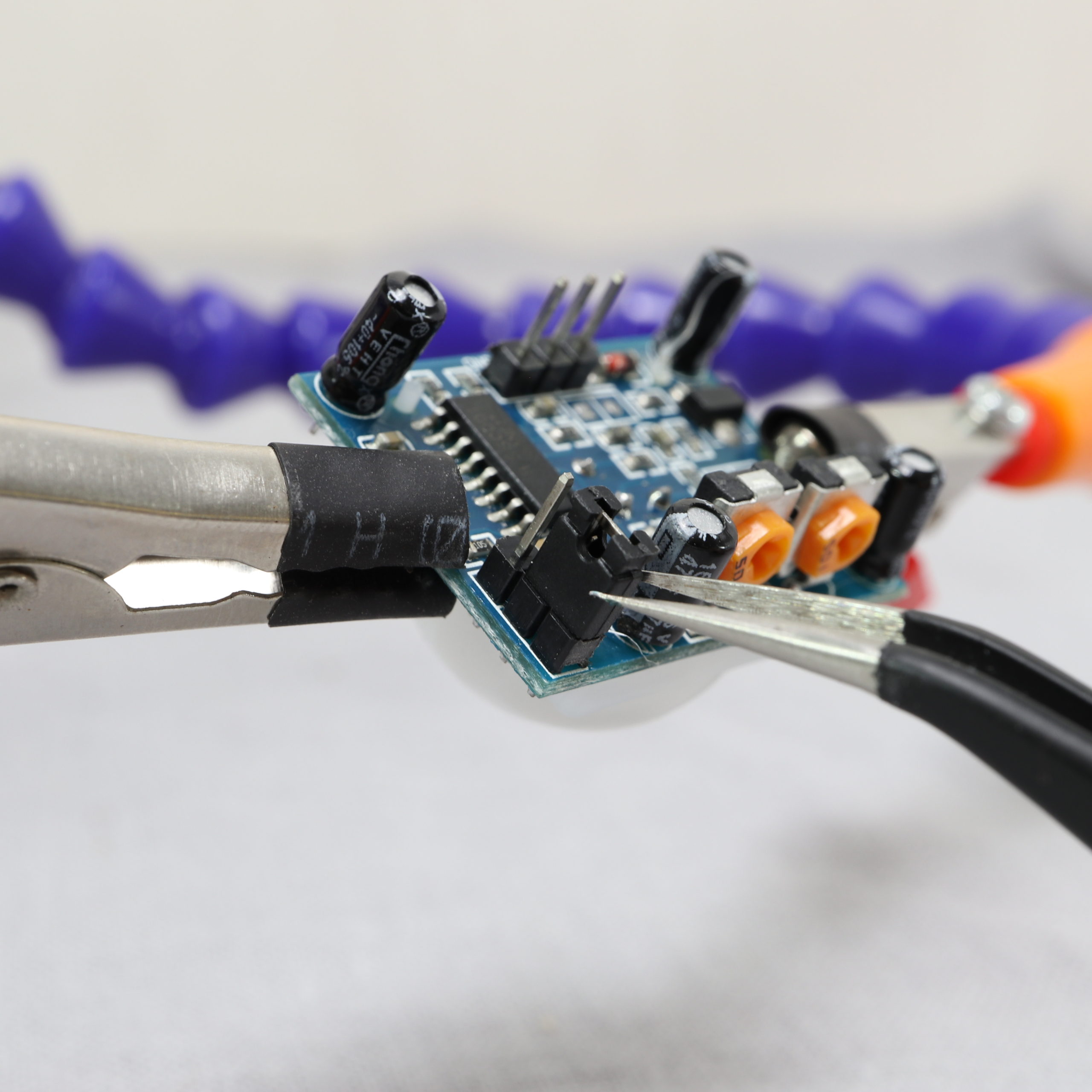
Lastly, the breakout board has a jumper to select between two trigger modes: single trigger or repeating trigger. For both modes, the output will turn “high” as soon as motion is detected. The signal will stay high for the time-delay adjusted by the potentiometer. In single trigger mode, further movement is not processed during this period (“timer for time-delay is not restarted”). In repeating trigger mode, any further movement is processed and time-delay is started again (“timer for time-delay is restarted”).
The operating voltage ranges from 5V to 20V DC. Moreover, the PCB has two holes to mount the breakout board to any type of installation (e.g. into a 3D-printed housing).
Example Application: Arduino Uno + HC-SR501 PIR Sensor
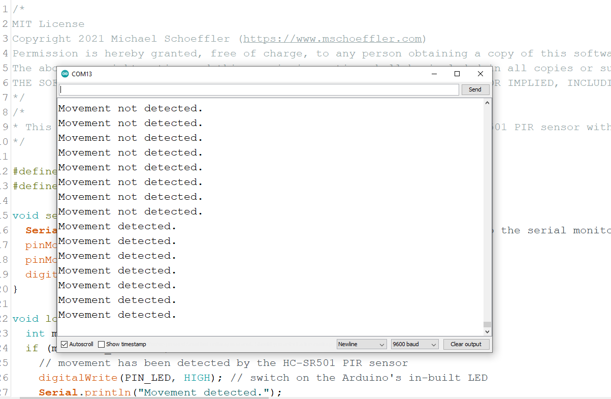
The idea of the example application is to wire the HC-SR501 PIR sensor to an Arduino. The Arduino Uno reads the output signal of the PIR sensor. The Arduino Uno prints the information whether movement has been detected or not to the serial monitor. In addition, the Arduino’s in-built LED is switched on, if movement is detected.
Once you have the example application running, you can play around with the adjustment options of the HC-SR501 to find the perfect settings for your application.
Wiring between Arduino Uno and HC-SR501
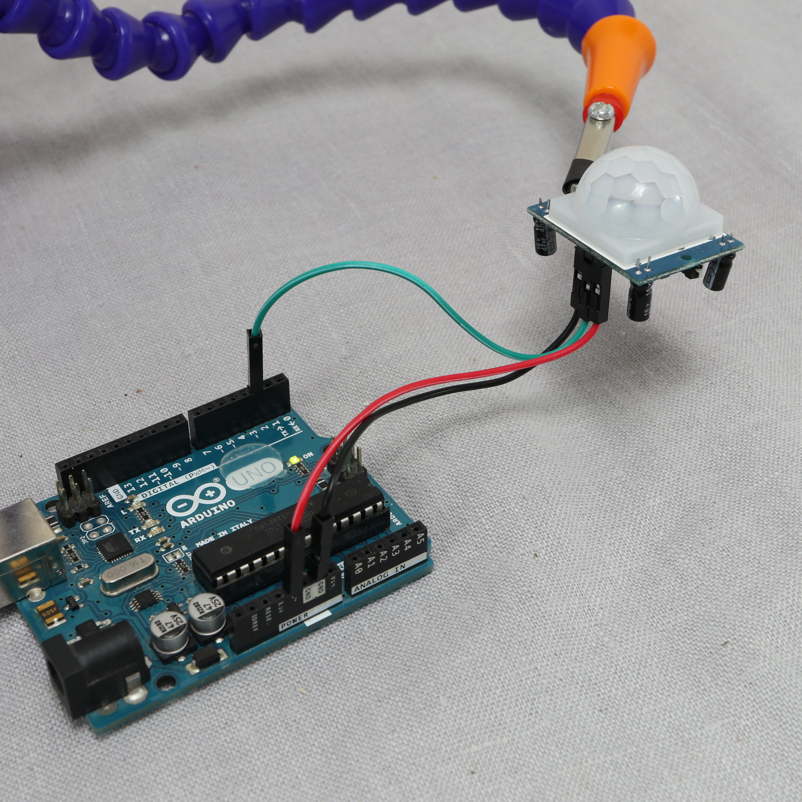
You need to make three connections between the Arduino Uno and HC-SR501 to make it work. First, wire one of the Arduino’s GND pins to the HC-SR501’s GND pin (black wire). Next, wire the Arduino’s 5V pin to the HC-SR501’s VCC pin (red wire). The last step is to wire the Arduino’s digital pin 2 to the HC-SR501’s OUT pin (green wire). Basically, you can use any of the Arduino’s digital pins for the sensor’s output signal. In this tutorial, we simply go with pin 2.
Programming movement detection
In the setup function, the serial connection is started. Moreover, the pin mode of digital pin 2 is set to “input”. The Arduino’s in-built LED is on pin 13, which is set to output mode.
In the loop function, the signal of the digital pin 2 is read. If the signal is “high”, movement has been detected. A message is printed out to the serial connection and the in-built LED is switched on. If the signal is “low”, another message is printed and the LED is switched off. At the end, there is a little delay in order to wait for a second until the loop function is called again.
/*
MIT License
Copyright 2021 Michael Schoeffler (https://www.mschoeffler.com)
Permission is hereby granted, free of charge, to any person obtaining a copy of this software and associated documentation files (the "Software"), to deal in the Software without restriction, including without limitation the rights to use, copy, modify, merge, publish, distribute, sublicense, and/or sell copies of the Software, and to permit persons to whom the Software is furnished to do so, subject to the following conditions:
The above copyright notice and this permission notice shall be included in all copies or substantial portions of the Software.
THE SOFTWARE IS PROVIDED "AS IS", WITHOUT WARRANTY OF ANY KIND, EXPRESS OR IMPLIED, INCLUDING BUT NOT LIMITED TO THE WARRANTIES OF MERCHANTABILITY, FITNESS FOR A PARTICULAR PURPOSE AND NONINFRINGEMENT. IN NO EVENT SHALL THE AUTHORS OR COPYRIGHT HOLDERS BE LIABLE FOR ANY CLAIM, DAMAGES OR OTHER LIABILITY, WHETHER IN AN ACTION OF CONTRACT, TORT OR OTHERWISE, ARISING FROM, OUT OF OR IN CONNECTION WITH THE SOFTWARE OR THE USE OR OTHER DEALINGS IN THE SOFTWARE.
*/
/*
* This example source code is part of a tutorial on how to use the HC-SR501 PIR sensor with an Arduino Uno.
*/

#define PIN_PIRSENSOR 2
#define PIN_LED 13

void setup() {
  Serial.begin(9600); // start serial connection to print out messages to the serial monitor
  pinMode(PIN_PIRSENSOR, INPUT);
  pinMode(PIN_LED, OUTPUT);
  digitalWrite(PIN_LED, LOW); // switch off the Arduino's in-built LED
}

void loop() {
  int movement_detected = digitalRead(PIN_PIRSENSOR);
  if (movement_detected) {
    // movement has been detected by the HC-SR501 PIR sensor
    digitalWrite(PIN_LED, HIGH); // switch on the Arduino's in-built LED
    Serial.println("Movement detected.");
  } else {
    digitalWrite(PIN_LED, LOW); // switch off the Arduino's in-built LED
    Serial.println("Movement not detected.");
  }
  delay(1000); // wait for one second until the next check
}
After transferring the program to an Arduino Uno, the in-built LED should light up as soon as you start to move in front of the sensor. In case the LED does not light up, try to adjust your sensor settings by turning the potentiometers.
In addition to the LED, a message about the detection should also appear on the serial monitor.