
A color sensor detects the color of incoming light with the help of photodiodes. There exist many color sensor breakout boards that often come with a TCS230 or a TCS3200 color light-to-frequency converter. This tutorial shows how such a color sensor can be utilized by an Arduino microcontroller.
Related products
Color Sensor (TCS230/TCS3200)
A color sensor typically consists of an array of photodiodes that is connected to a current-to-frequency converter. For example, TCS230 and TCS3200 modules have an 8 x 8 array of photodiodes, where 16 photodiodes have blue filters, 16 photodiodes have green filters, 16 photodiodes have red filters, and 16 photodiodes are clear with no filters.

Besides the typical VCC and GND pins for the power supply, the color sensor breakout boards have many special pins. The color sensor has two pins (S2 and S3) that are used to select a type out of the photodiode types (blue, green, red and clear). TCS230- and TCS3200-based color sensors have two more pins to control the scaling of the output frequency. In particular, the frequency can be adjusted to three different presets: 2%, 20% and 100%. The adjustment of the frequency scaling is used to optimize the output of the sensor for different frequency counters or microcontrollers. Furthermore, the output enable pin (OE) places the output in the high-impedance state for multiple-unit sharing of a microcontroller input line (not used in this tutorial). The OUT pin is used to read the current sensor value.
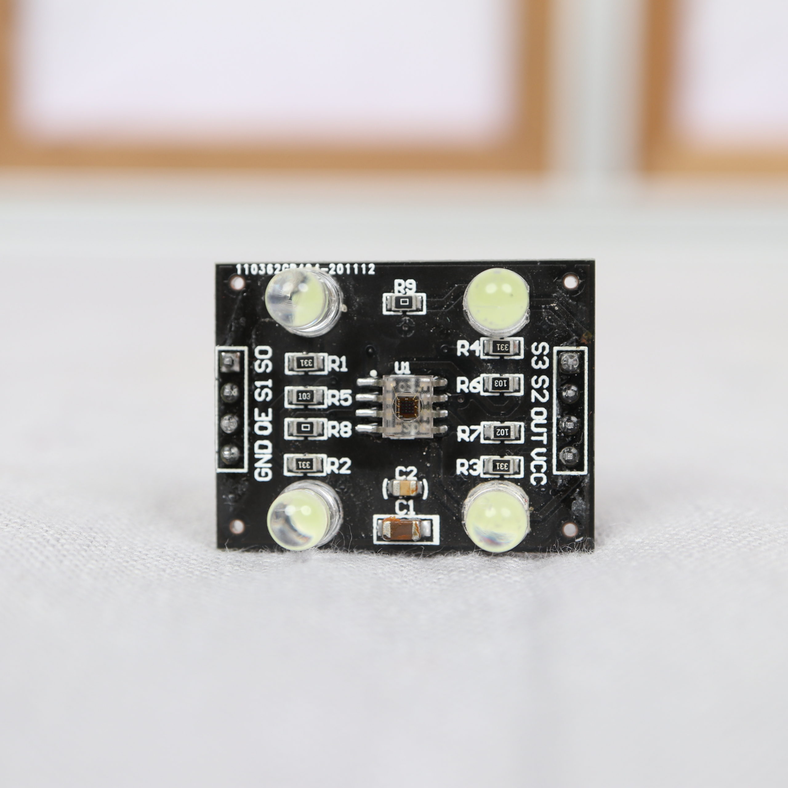
The next tables show how the photodiode control (S2, S3) and the scaling (S0, S1) can be controlled.
| Pin S0 | Pin S1 | OUTPUT FREQUENCY SCALING |
|---|---|---|
| 0 | 0 | Power down |
| 0 | 1 | 2% |
| 1 | 0 | 20% |
| 1 | 1 | 100% |
| Pin S2 | Pin S3 | PHOTODIODE TYPE |
|---|---|---|
| 0 | 0 | Red |
| 0 | 1 | Blue |
| 1 | 0 | Clear |
| 1 | 1 | Green |
Btw. there are minor differences between TCS230- and TCS3200-based color sensors (e.g. operating temperatures). Normally, the differences make no differences for typical “maker use cases”. You find all the details in the corresponding data sheets.
Wiring between Arduino and Color Sensor
In order to supply power to the module, the Arduino’s 5V and GND must be wired to the modules VCC and GND pin. To control the color sensor module, the module’s S0, S1, S2, and S3 pins are wired to the Arduino’s digital pin 2, 3, 4 and 5. The module’s output pin is wired to Arduino’s digital pin 6.

| Arduino’s Pin | Wire color | Color Sensor Pin | Color Sensor Pin Description |
|---|---|---|---|
| GND | black | GND | Power supply ground. All voltages are referenced to GND. |
| 5V | red | VCC | Supply voltage |
| Digital #2 | blue | S0 | Output frequency scaling selection inputs |
| Digital #3 | green | S1 | Output frequency scaling selection inputs |
| Digital #4 | orange | S2 | Photodiode type selection inputs |
| Digital #5 | yellow | S3 | Photodiode type selection inputs |
| Digital #6 | white | OUT | Output frequency |
| – | – | OE (unused) | Enable for output frequency (active low) |
Arduino and Color Sensor Code Example
The following code example shows how to read color values from the sensor in order to print them to the serial monitor.
In the setup function, pin modes are set and the frequency scaling is adjusted to 20%. If you require a different frequency scaling, set the S0 and S1 values to different states (see previous output frequency scaling table).
The loop function has three parts: 1) reading the red value, 2) reading the green value and 3) reading the blue values. Each part has basically the same procedure: The S2 and S3 pin are set to select the corresponding filtered photodiode type. Then, the color values is read with the help of the Arduino’s pulseIn-function. Lastly, the color value are printed via the serial connection.
/*
MIT License
Copyright 2021 Michael Schoeffler (https://www.mschoeffler.com)
Permission is hereby granted, free of charge, to any person obtaining a copy of this software and associated documentation files (the "Software"), to deal in the Software without restriction, including without limitation the rights to use, copy, modify, merge, publish, distribute, sublicense, and/or sell copies of the Software, and to permit persons to whom the Software is furnished to do so, subject to the following conditions:
The above copyright notice and this permission notice shall be included in all copies or substantial portions of the Software.
THE SOFTWARE IS PROVIDED "AS IS", WITHOUT WARRANTY OF ANY KIND, EXPRESS OR IMPLIED, INCLUDING BUT NOT LIMITED TO THE WARRANTIES OF MERCHANTABILITY, FITNESS FOR A PARTICULAR PURPOSE AND NONINFRINGEMENT. IN NO EVENT SHALL THE AUTHORS OR COPYRIGHT HOLDERS BE LIABLE FOR ANY CLAIM, DAMAGES OR OTHER LIABILITY, WHETHER IN AN ACTION OF CONTRACT, TORT OR OTHERWISE, ARISING FROM, OUT OF OR IN CONNECTION WITH THE SOFTWARE OR THE USE OR OTHER DEALINGS IN THE SOFTWARE.
*/
/*
* Example source code of an Arduino tutorial on how to read color values from a TCS230/TCS3200 Color Sensor.
*/
// pin definitions
#define PIN_S0 2
#define PIN_S1 3
#define PIN_S2 4
#define PIN_S3 5
#define PIN_OUT 6
void setup() {
Serial.begin(9600); // initialize serial
// set pin modes
pinMode(PIN_S0, OUTPUT);
pinMode(PIN_S1, OUTPUT);
pinMode(PIN_S2, OUTPUT);
pinMode(PIN_S3, OUTPUT);
pinMode(PIN_OUT, INPUT);
// set the frequency scaling to 20% (S==1; S1=0)
digitalWrite(PIN_S0,HIGH);
digitalWrite(PIN_S1,LOW);
}
void loop() {
// select photodiodes with red filters
digitalWrite(PIN_S2, LOW);
digitalWrite(PIN_S3, LOW);
int frequency_red = pulseIn(PIN_OUT, LOW); // read red output frequency
// print out red frequency value via serial
Serial.print("Red = ");
Serial.print(frequency_red);
Serial.print("; ");
delay(100); // short delay between readings
// select photodiodes with green filters
digitalWrite(PIN_S2, HIGH);
digitalWrite(PIN_S3, HIGH);
int frequency_green = pulseIn(PIN_OUT, LOW); // read green output frequency
// print out green frequency value via serial
Serial.print("Green = ");
Serial.print(frequency_green);
Serial.print("; ");
delay(100); // short delay between readings
// select photodiodes with blue filters
digitalWrite(PIN_S2, LOW);
digitalWrite(PIN_S3, HIGH);
int frequency_blue = pulseIn(PIN_OUT, LOW); // read blue output frequency
// print out blue frequency value via serial
Serial.print("Blue = ");
Serial.println(frequency_blue);
delay(100); // short delay between readings
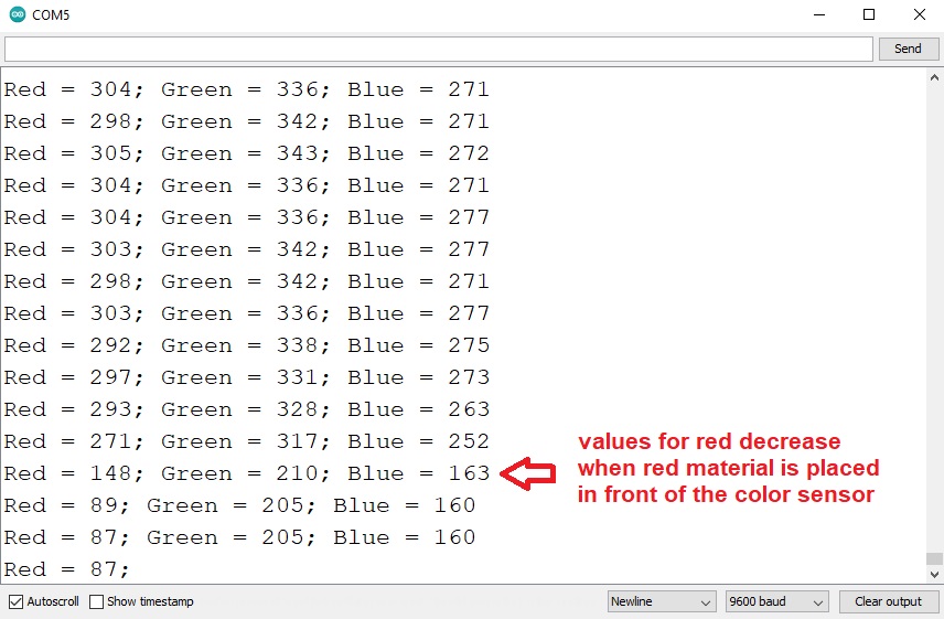
}The values you get out for each color are not normalized (e.g. from 0 to 255). In fact, these color values are influenced by your personal microcontroller setup, lighting, color material etc. In order to normalize them, it makes sense to test the color sensor first with different colored materials. This helps you to find out your individual lowest and highest values for each color. Next, you can use e.g. the map function to normalize the color values as you like (e.g. to a scale from 0 to 255).
Keep in mind, a color value gets lower if the corresponding color is present. For example, I tried out my code by holding some red material in front of the color sensor. At the same time, the red value significantly decreased.

HI Michael .
I have a problem with amount of output of sensor . in datasheet the output of f0 for red color is 14 19 24 kHZ but your and mine output isn’t like that ? ( your is 163 KHZ) . i don’t khnow where is my problem . please Guidance me thnaks thanks thanks