
A servo motor allows to precisely control a shaft to a specific rotary position. The MG 996R is one of the most popular servo motors within the maker community. This tutorial shows how to wire the MG 996R servo to an Arduino. Moreover, this tutorials includes a simple code example that let’s the motor rotate to various rotary positions.
Related products
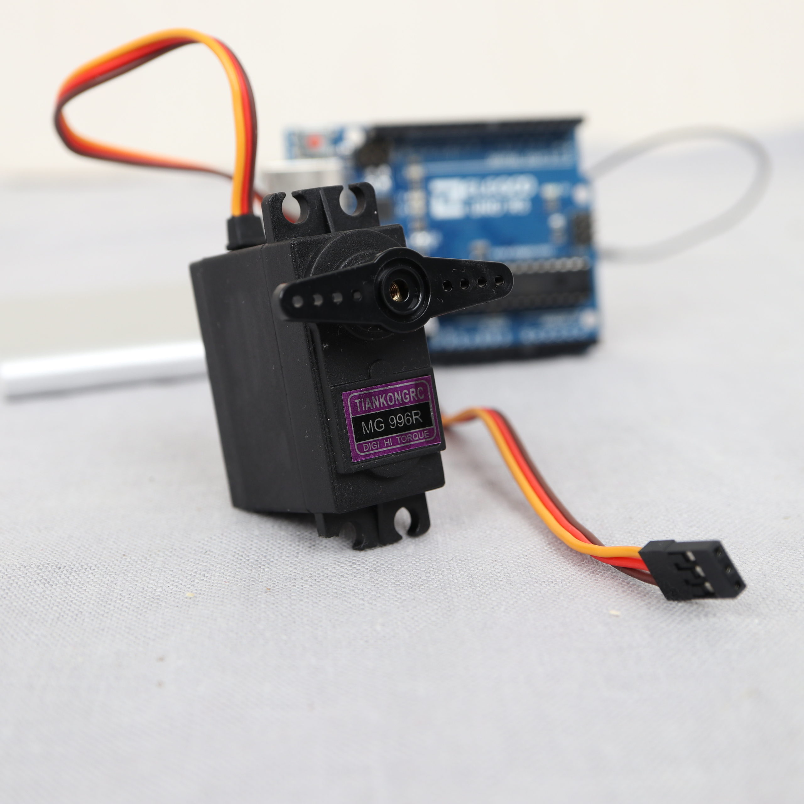
MG 996R Servo Motor
The MG 996R is a popular servo motor within the Arduino Community. In contrast to the likewise popular SG90 servo, the MG 996R is able to rotate much higher weights. For example, you can see the MG 996R very frequently in 3D-printed robotic arm applications.
Technical specification
| Name | Value |
|---|---|
| Dimensions | ca. 40.7 x 19.7 x 42.9 mm |
| Weight | ca. 55g |
| Operating voltage | 4.8 V – 6.6 V |
| Operating current | ca. 600 – 1500mA |
| Stall torque | 9.4 kg/cm (4.8V); 11 kg/cm (6V) |
| Operating speed | 0.19 s/60º (4.8 V), 0.15 s/60º (6 V) |
| Angle | 0-180° |
Example application
The example application is kept very simple. The motor rotates to four different positions with a delay of one second in between. If the motor has completed the last position, the sequence starts again.
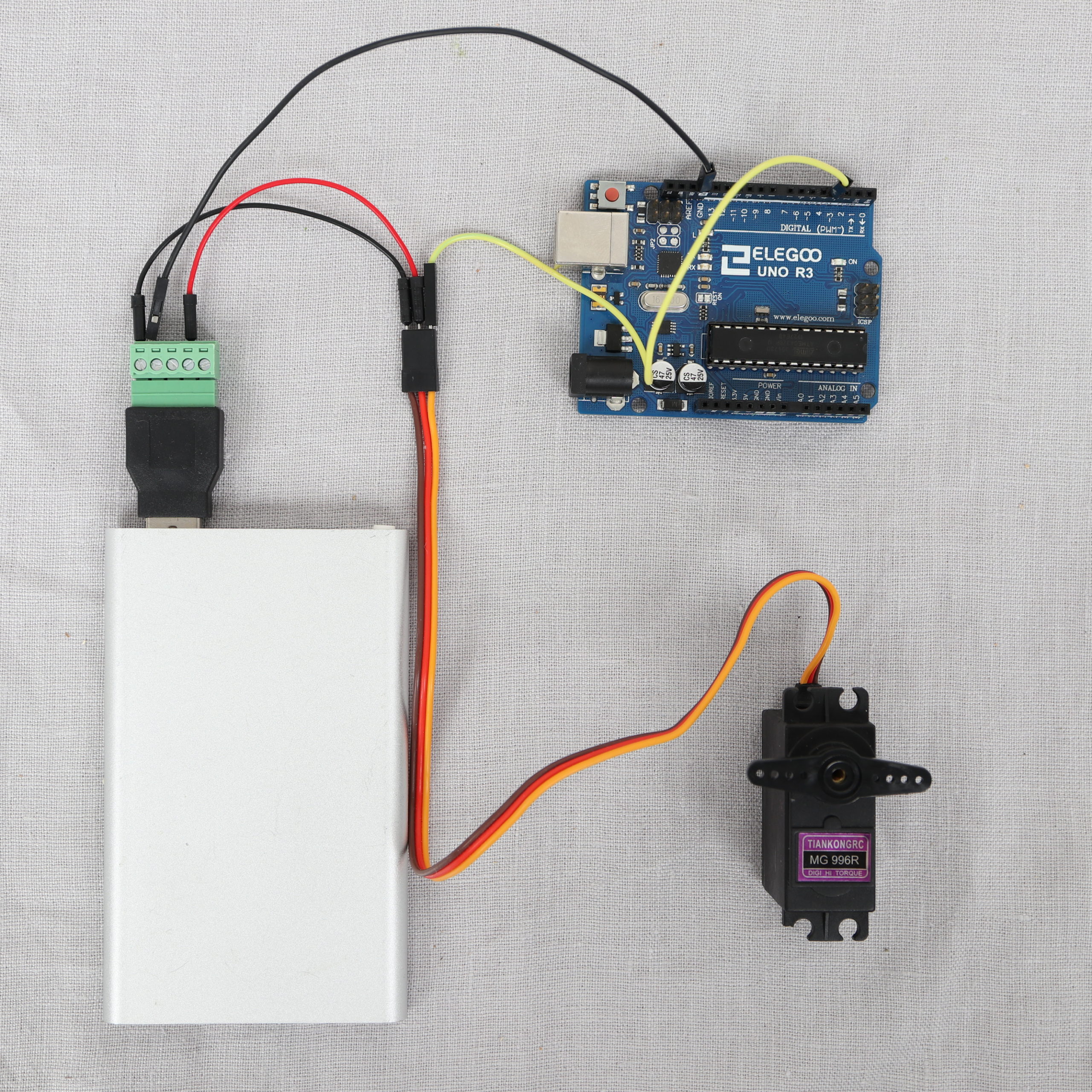
Wiring
The motor has three wires: Brown (GND), Red (+5V) and Orange (PWM signal). Unfortunately, the motor can’t be directly powered from the Arduino. The motor will likely draw to much current from the Arduino. As a consequence, the Arduino might get damaged. In order to overcome this problem, I wired the motor to an external power supply.
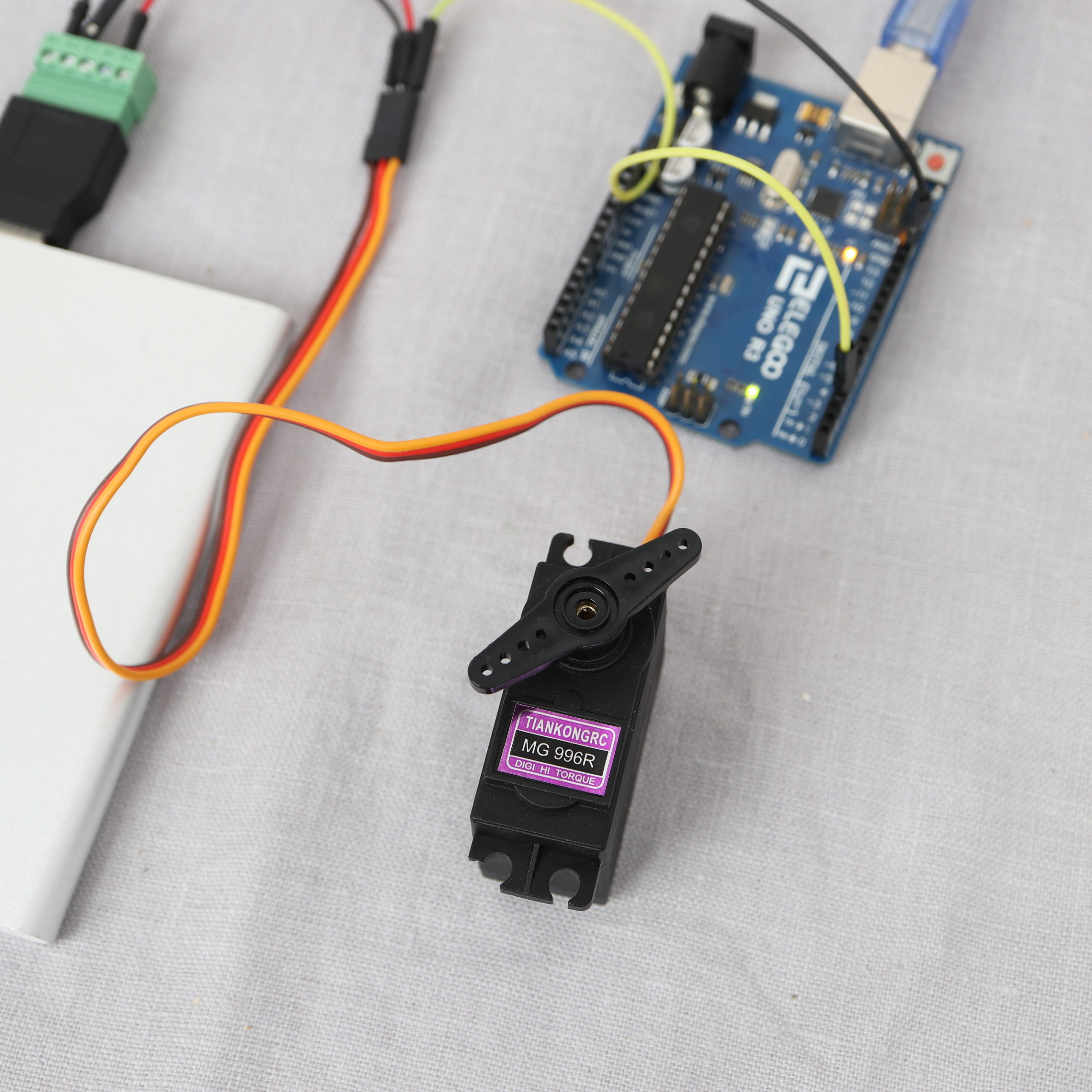
In particular, I took a 5V USB power supply (power bank) to power the motor. For the wiring, I made use of a USB terminal adapter. The “-” signal from the USB terminal adapter is wired to the brown input of the servo motor. Accordingly, the “+” signal is wired to the servo’s red input. In order to guarantee the same signal level, the terminal adapter’s “-” signal is wired to one of the Arduino’s GND pins. Luckily, it is easily possible to connect two male jumper wires to a single terminal block of the adapter.
Next, Arduino’s pin #3 is wired to the orange input of the servo motor.
| MG 996R wire color | Description | Connected to |
|---|---|---|
| Brown | GND | USB Power Bank “-” and Arduino GND |
| Red | +5V (Powering the motor directly from the Arduino, might damage the Arduino) | USB Power Bank “+” |
| Orange | PWM signal | Arduino Pin #3 |
Example source code
I made use of the servo library to control the MG 996R motor. In the setup function, pin number 3 is made known to the servo object.
In the loop function, the motor is rotated to four different positions by the write method.
/*
MIT License
Copyright 2021 Michael Schoeffler (https://www.mschoeffler.com)
Permission is hereby granted, free of charge, to any person obtaining a copy of this software and associated documentation files (the "Software"), to deal in the Software without restriction, including without limitation the rights to use, copy, modify, merge, publish, distribute, sublicense, and/or sell copies of the Software, and to permit persons to whom the Software is furnished to do so, subject to the following conditions:
The above copyright notice and this permission notice shall be included in all copies or substantial portions of the Software.
THE SOFTWARE IS PROVIDED "AS IS", WITHOUT WARRANTY OF ANY KIND, EXPRESS OR IMPLIED, INCLUDING BUT NOT LIMITED TO THE WARRANTIES OF MERCHANTABILITY, FITNESS FOR A PARTICULAR PURPOSE AND NONINFRINGEMENT. IN NO EVENT SHALL THE AUTHORS OR COPYRIGHT HOLDERS BE LIABLE FOR ANY CLAIM, DAMAGES OR OTHER LIABILITY, WHETHER IN AN ACTION OF CONTRACT, TORT OR OTHERWISE, ARISING FROM, OUT OF OR IN CONNECTION WITH THE SOFTWARE OR THE USE OR OTHER DEALINGS IN THE SOFTWARE.
*/
/*
* Example source code of an Arduino tutorial on how to control an MG 996R servo motor.
*/

#include <Servo.h>

Servo servo; // servo object representing the MG 996R servo

void setup() {
  servo.attach(3); // servo is wired to Arduino on digital pin 3
}

void loop() {
  servo.write(0); // move MG996R's shaft to angle 0°
  delay(1000); // wait for one second
  servo.write(45); // move MG996R's shaft to angle 45°
  delay(1000); // wait for one second
  servo.write(90); // move MG996R's shaft to angle 90°
  delay(1000); // wait for one second
  servo.write(135); // move MG996R's shaft to angle 135°
  delay(1000); // wait for one second
  servo.write(180); // move MG996R's shaft to angle 180°
  delay(1000); // wait for one second
}
If everything has been correctly executed, the motor should start moving.
It can turn around from degree zero to degree 360.
Thank you for your simple explanation! I might even be able to do this. First let me say I have zero experience with these items and doing this. I just have a little project I’m working on and I’m trying to keep it simple as possible. ok so my first question is the program you use to program the Arduino does it automatically come up when i plug it into my PC? Second, given your simple layout of how to hook this all together how would i wire in a simple on off switch?
thanks for your help!
hey i was wonderig where i can find the adapter that you used for the power bank