
Power supply unit (PSU) breakout boards are useful equipment, e.g. when it comes to test ATX-compatible PSUs. These breakout boards have a PCB header for the PSU connector. The signals of the PSU connector are directed to terminal blocks. As a result, it’s very simple to check whether the correct voltage levels are held on each terminal block. Besides testing PSUs, these breakout boards can serve as power supply, e.g. for microcontroller prototyping. ATX power supplies offer voltage levels of 3.3V, 5V and 12V. Especially if you have some discarded PSUs, it might worth a look to reuse them as power supply for prototyping.
Related products
| ATX Power supply (silent) | |
| PSU breakout board D-1188 | |
| Multimeter (Fluke 175) | |
| Microcontroller | |
| DSO138 oscilloscope |
PSU Breakout Board D-1188
The PSU breakout board D-1188 is probably the most known breakout board for ATX power supplies. The D-1188 board has a PCB header that supports ATX 20-Pin and ATX 24-Pin (ATX 20+4-Pin) connectors. Each connector pin signal is directed to a different terminal block.
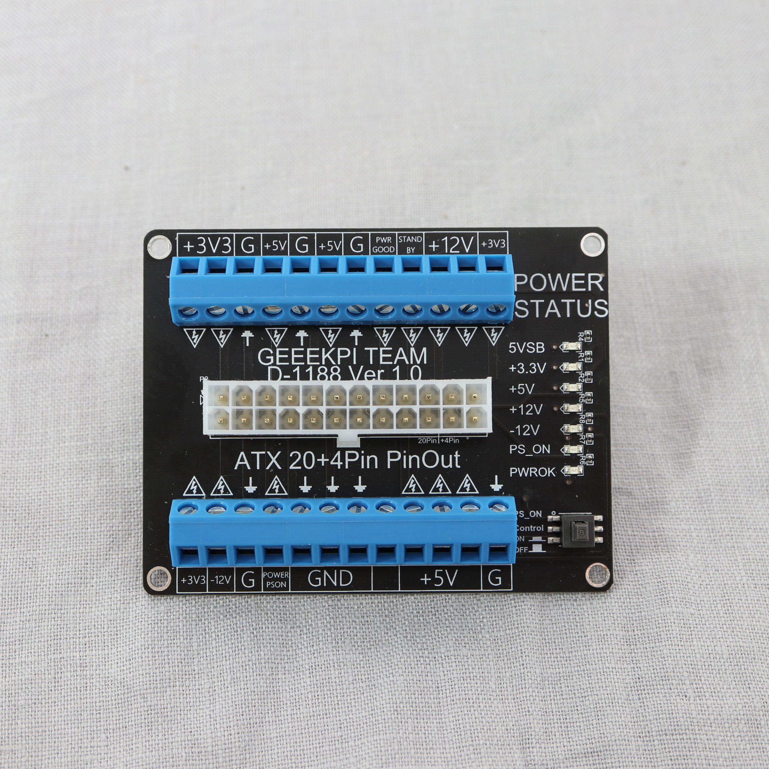
The D-1188 board allows to quickly inspect the various signal states. On the board’s right-hand side are 7 LEDs that show the status of the 5VSB, +3.3V, +5V, +12V, -12V, PS_ON and PWROK/PWR_OK signal.
Normally, you must connect the PS_ON signal to GND in order to turn on an ATX power supply. The D-1188 board has a switch that does the job for you. By pressing the switch, you can turn on/off the PSU.
Testing/Checking a PSU
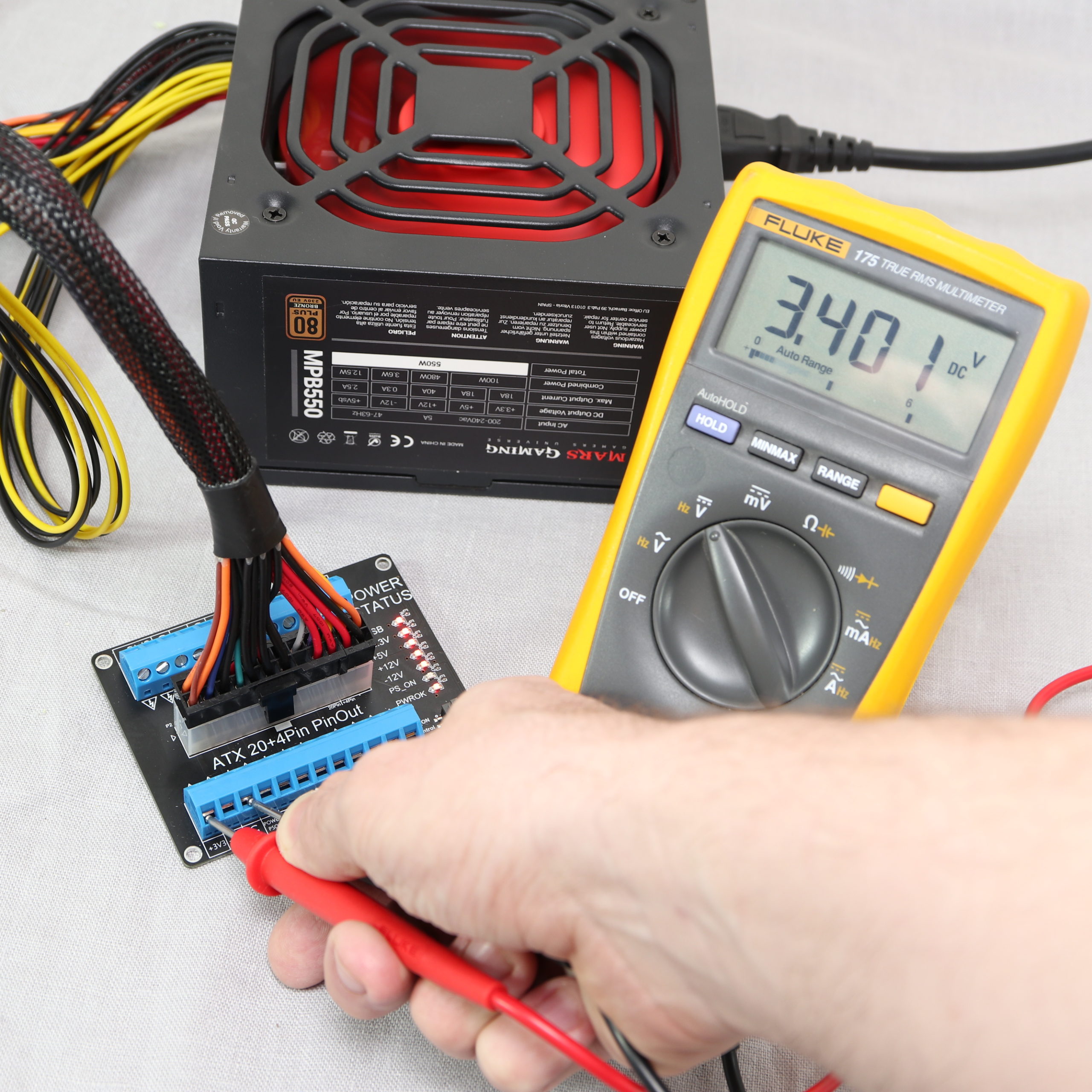
The breakout board can be used for testing PSUs. For example, the terminal blocks can be connected to a multimeter in order to check for the specific voltage levels. As mentioned before, the board’s LEDs give you a good indication about the provided voltage levels. Nonetheless, you can recheck the signals with a multimeter more accurately.
With the breakout board, it’s also possible to monitor a signal over time. For example, you can use a DS0138 oscilloscope to monitor the PWROK signal (also called “power good signal”). The signal indicates to the motherboard that all of the provided voltages are within specification and that the system may proceed to boot and operate. After turning on the PSU, the PWROK signal should switch from LOW to HIGH.

Power supply for microcontroller prototyping
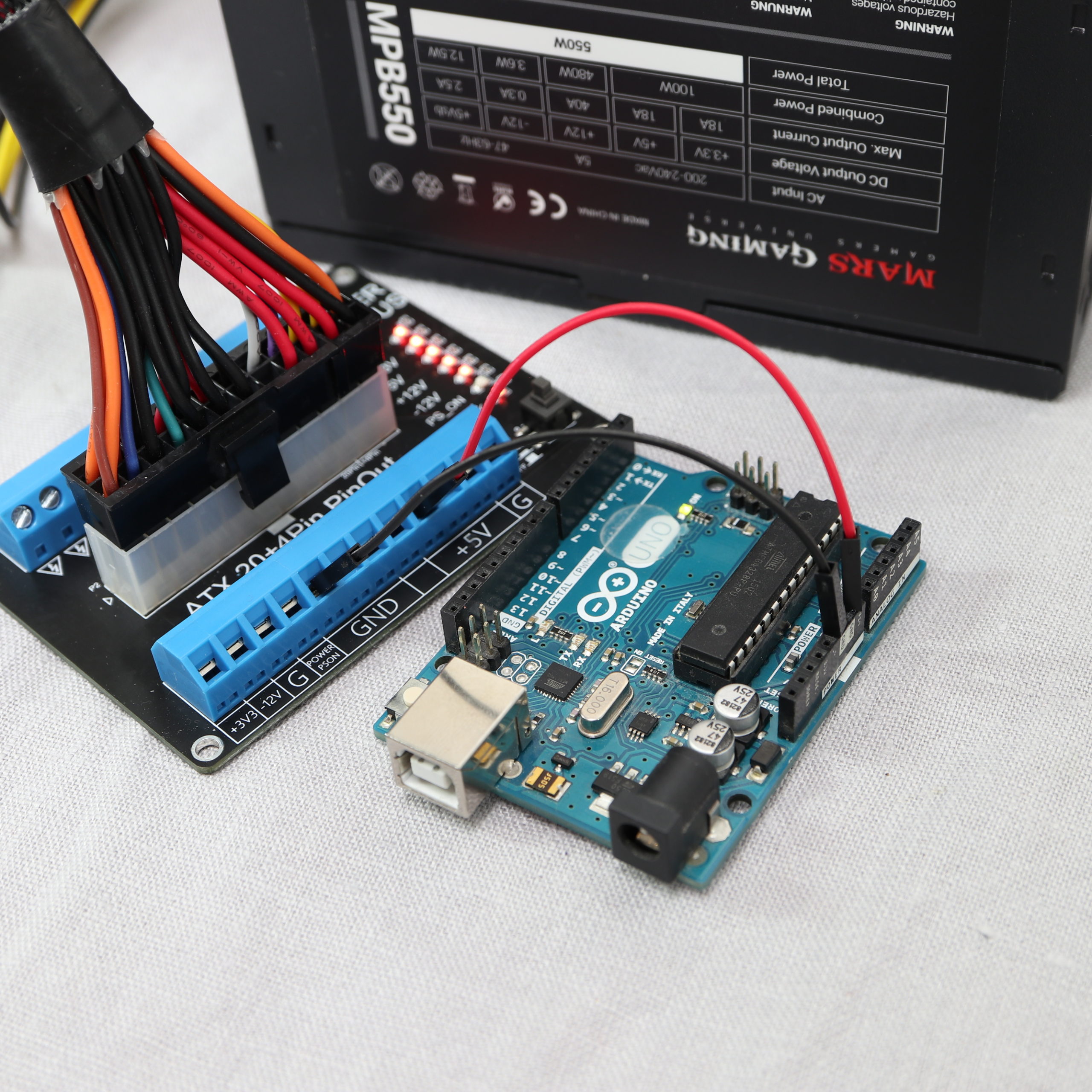
An ATX power supply in combination with a D-1188 breakout board simultaneously provides typical voltage levels for prototyping, such as 3.3V and 5V. Actually, I use this combination quite often. I have one of these silent ATX power supplies which makes working with them very comfortable.
Please keep in mind that ATX power supplies are meant to be placed inside PC cases. Therefore, the life-threatening voltages inside a power supply (110V/220V AC) are not fully protected against the “outside world” in all possible scenarios. It might be possible to accidently reach the inner parts of a power supply, e.g. with a thin screwdriver. Therefore, please take some precautions to avoid reaching the inner parts when working one something.

Bonjour!
J’ai acheté cette carte de dérivation pour une alimentation ATX 20 + 4 broches (D-1188 Ver 1.0) qui alimente une motorisation de persiennes commandée à distance et gérée par un programme arduino.
Je voudrais activer cette alimentation via le programme Arduino, sans utiliser l’interrupteur on/off
de la carte de dérivation. J’ai tenté de commander la mise à 0v de la broche PS_ON par le programme mais cela ne fonctionne pas! Pouvez-vous m’aider?
Merci d’avance