
AL-ZARD’s DST-1R4P-N is an optocoupler isolation board that comes in handy if you need to convert an electrical digital signal from one voltage level into another voltage level. A typical example is a digital 24V signal of an industrial sensor that has to be read by an ESP32 microcontroller. An ESP32 expects a voltage level of 3.3V.
The DST-1R4P-N board is available in different variants where each variant has been made for a specific voltage conversion (e.g. 24V to 3.3V, 12V to 3.3V, 5V to 3.3V,…).
Related products
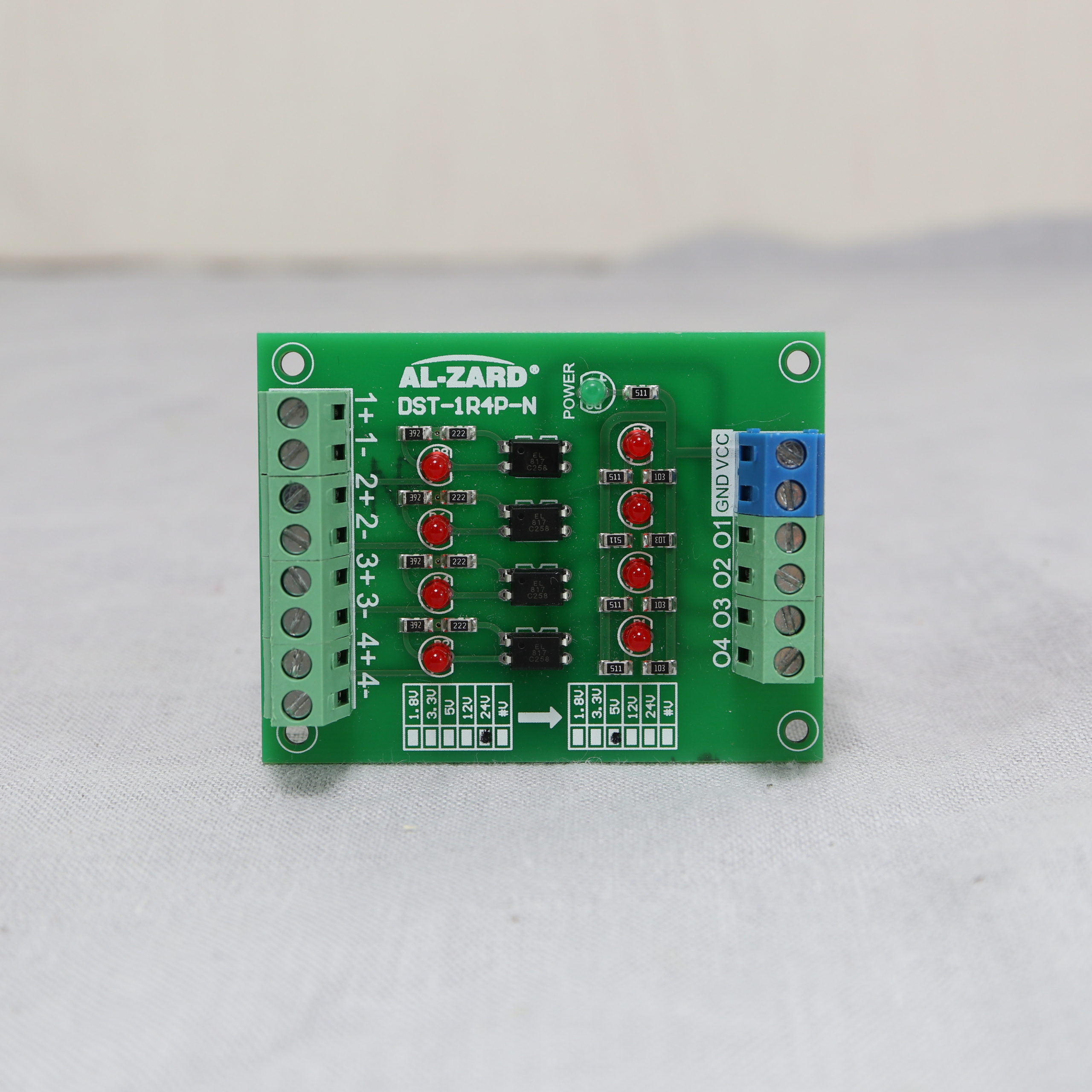
DST-1R4P-N Board
The DST-1R4P-N has four channels, i.e. up to four different digital signals can be converted at the same time. Each channel comes with two (red) LEDs. The first LED indicates whether there is a high signal on the input, the second LED shows the same for the output. In order to grab output signals, the board must be powered with the output voltage. There are two terminal block to wire GND and VCC to the board. Moreover, next to the terminal blocks is a (green) LED that shows the current power status.
The actual conversion done is by EL817 DIPs (dual in-line packages), which are 4-pin phototransistor photocoupler modules. Since each channel has its own EL817, you find four EL817 DIPs on the board.
Pin Definitions
As mentioned before, the DST-1R4P-N comes in different variants. Normally, the input voltage and output voltage is marked on the board. The output voltage and the module voltage are the same.
| Type | Pin Name | Description |
|---|---|---|
| Input | 1+ | Positive input signal of first channel |
| Input | 1- | Negative input signal of first channel |
| Input | 2+ | Positive input signal of second channel |
| Input | 2- | Negative input signal of second channel |
| Input | 3+ | Positive input signal of third channel |
| Input | 3- | Negative input signal of third channel |
| Input | 4+ | Positive input signal of fourth channel |
| Input | 4- | Negative input signal of fourth channel |
| Module | VCC | VCC to power module |
| Module | GND | Ground to power module (same GND as output signals) |
| Output | O1 | Output signal of first channel |
| Output | O2 | Output signal of second channel |
| Output | O3 | Output signal of third channel |
| Output | O4 | Output signal of fourth channel |
DST-1R4P-N and Microcontrollers (Arduino, ESP8266, ESP32,…)
If you plan to use the optocoupler isolation board with an Arduino, ESP32-based or any other microcontroller, keep in mind that the board triggers a LOW signal on the outputs if the inputs are high. If you work the first time with such a board, this might be confusing.
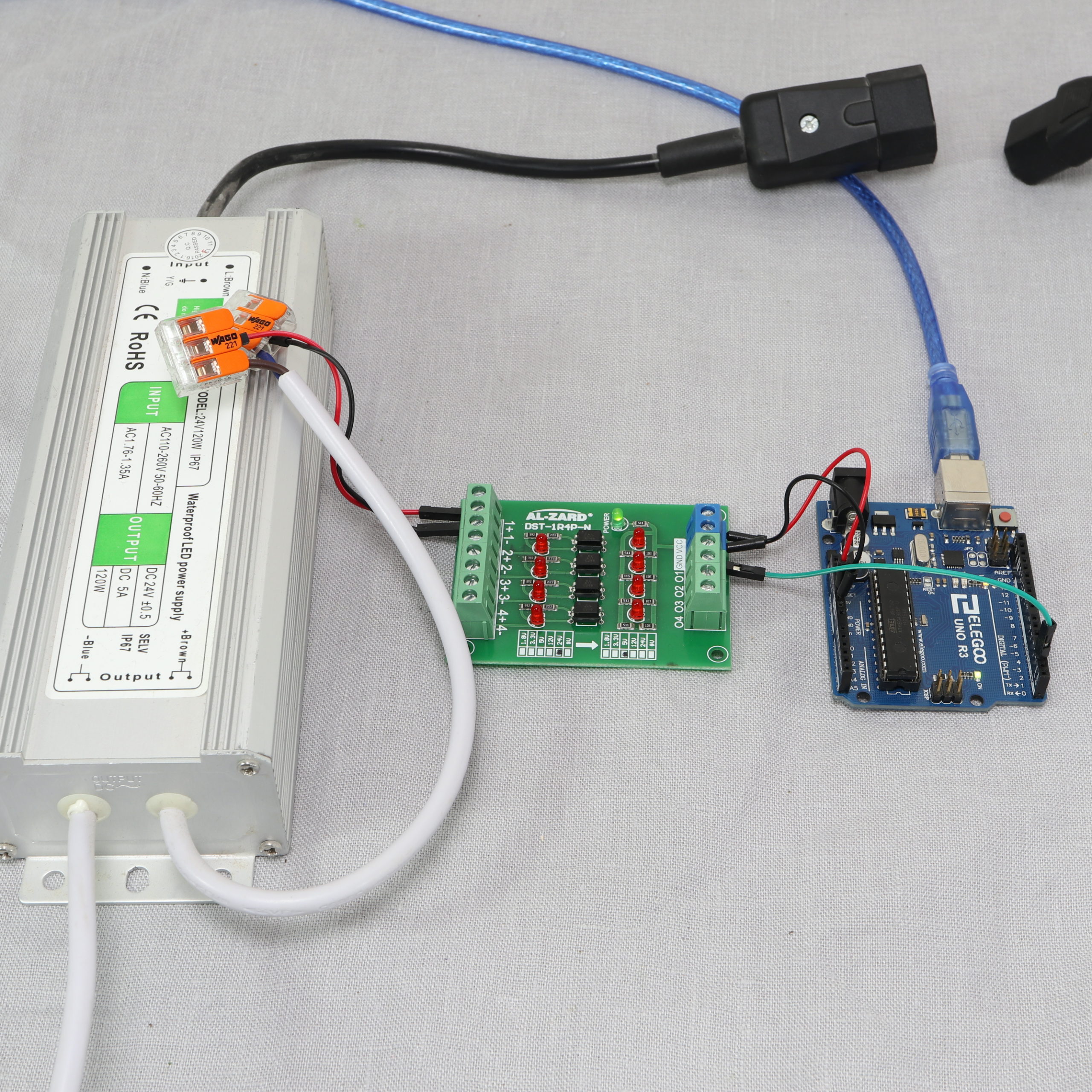
In the following, a very simple example is presented on how to use the board with an Arduino Uno. The approach can also be used, if another type of microcontroller (e.g. ESP8266 or ESP32 devkits) is used.
The idea is that a 24V power supply is wired to the optocoupler board. The Arduino Uno’s task is to detect whether the power supply is switched on.
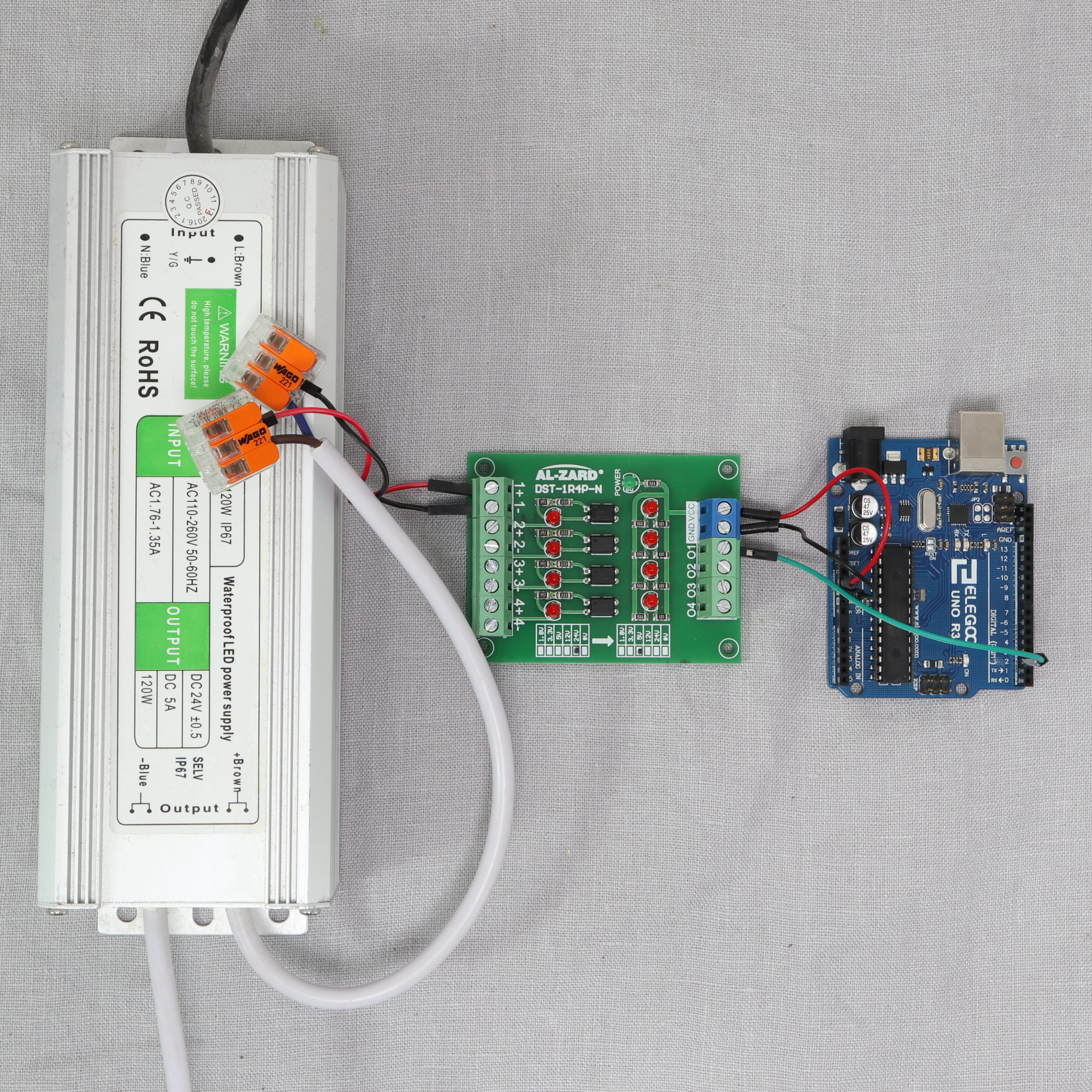
Wiring
The 24V power supply is wired to the DST-1R4P-N board. The power supply’s +24V signal goes to the 1+ terminal block of the board. The power supply’s ground signal goes to the 1- terminal block.
The Arduino’s 5V and GND pin go to the board’s VCC and GND terminal blocks. Lastly, the board’s first channel output “O1” is wired to the Arduino’s digital pin 2.
Programming
The usage of the optocoupler board is basically similar to reading the state of the button. First, set the pin mode to INPUT_PULLUP in the setup function. In the loop function, simply read the value of the pin. As mentioned before, if the value is ‘low’ the actual digital signal on the corresponding input channel is ‘high’.
/*
MIT License
Copyright 2021 Michael Schoeffler (https://www.mschoeffler.com)
Permission is hereby granted, free of charge, to any person obtaining a copy of this software and associated documentation files (the "Software"), to deal in the Software without restriction, including without limitation the rights to use, copy, modify, merge, publish, distribute, sublicense, and/or sell copies of the Software, and to permit persons to whom the Software is furnished to do so, subject to the following conditions:
The above copyright notice and this permission notice shall be included in all copies or substantial portions of the Software.
THE SOFTWARE IS PROVIDED "AS IS", WITHOUT WARRANTY OF ANY KIND, EXPRESS OR IMPLIED, INCLUDING BUT NOT LIMITED TO THE WARRANTIES OF MERCHANTABILITY, FITNESS FOR A PARTICULAR PURPOSE AND NONINFRINGEMENT. IN NO EVENT SHALL THE AUTHORS OR COPYRIGHT HOLDERS BE LIABLE FOR ANY CLAIM, DAMAGES OR OTHER LIABILITY, WHETHER IN AN ACTION OF CONTRACT, TORT OR OTHERWISE, ARISING FROM, OUT OF OR IN CONNECTION WITH THE SOFTWARE OR THE USE OR OTHER DEALINGS IN THE SOFTWARE.
*/
/*
* This example source code is part of an tutorial on how to use the optocoupler isolation board DST-1R4PN with an Arduino Uno.
*/
#define PIN_O1 2 // pin wired to the first output of the DST-1R4PN board
void setup() {
Serial.begin(9600);
pinMode(PIN_O1, INPUT_PULLUP); // set to pullup mode
}
void loop() {
int state_O1 = digitalRead(PIN_O1);
if (state_O1 == LOW) {
Serial.println("Output O1: HIGH"); // If state is LOW, a HIGH signal is received on the board's input
} else {
Serial.println("Output O1: LOW");
}
delay(5000);
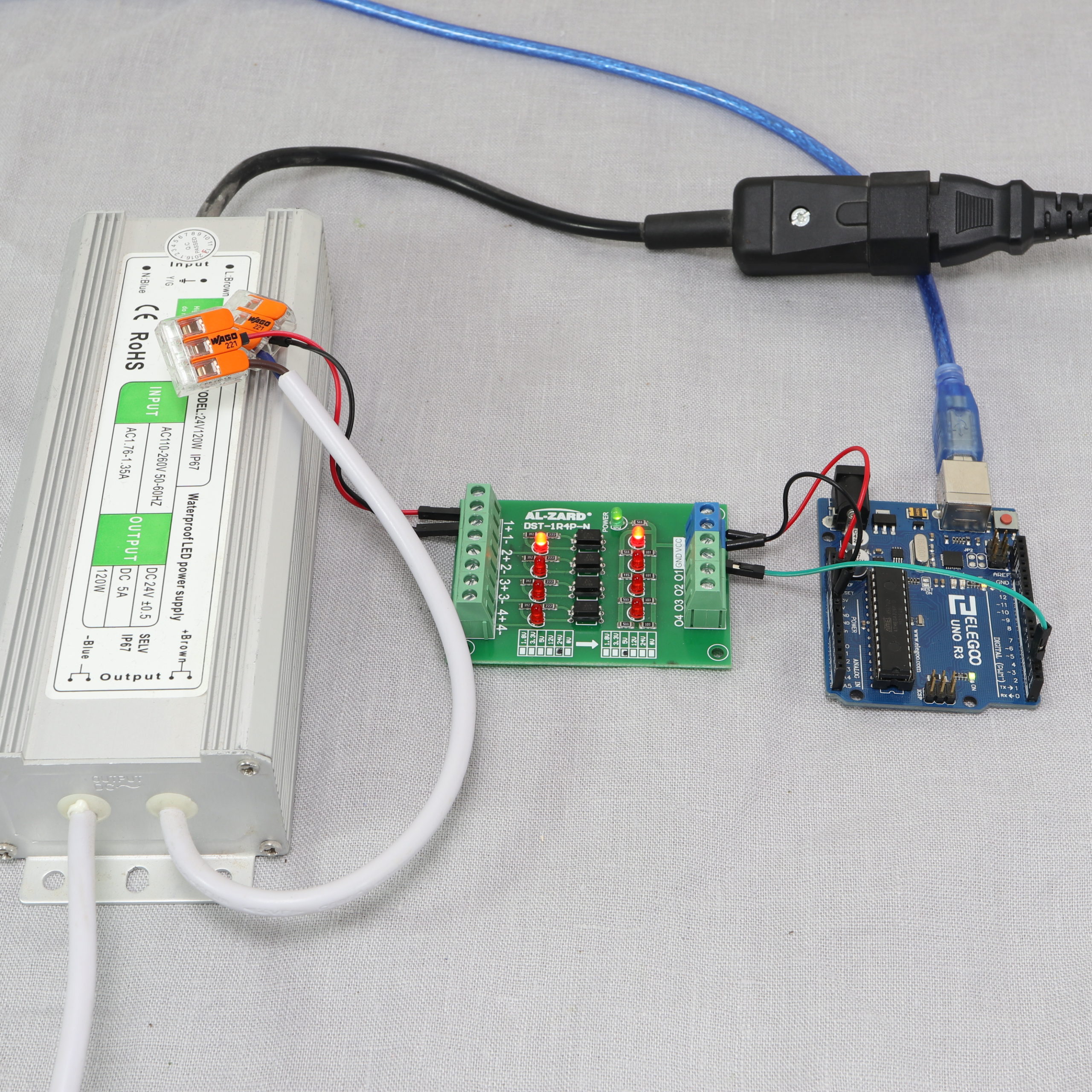
}If you transfer the program to an Arduino Uno, you should be able to see the message “Output O1: HIGH” as soon as a digital high signal is received on the input side.
To try it out, I plugged in my 24V power supply which triggers then a high signal:

Additional remarks
- The board exists also in other variants with respect to the number of channels. The functionality and pin definitions are basically the same except for the difference in channels
- DST-1R1P-N: 1-channel board
- DST-1R2P-N: 2-channel board
- DST-1R8P-N: 8-channel board
Excellent tutorial which covered all the points I wanted to know.
The high in/low out signal arrangement was a surprise to me, as was the INPUT_PULLUP code in the tutorial which I have not used before.
Keep doing tutorials like this, it is much appreciated by hobbyists and Arduino users.
Hi.
My board reads 5V and 3.1V on the output, which means the input pin (2 in your case) is always high. I’m using a 5V -> 5V optocoupler with inductive switches on inputs. Do you think there may be something wrong with the board or am I likely to be missing something?