In a previous blog post, I wrote a short tutorial about the GY-521 module (MPU-6050 breakout board). In addition to the blog post, I made a video tutorial that had basically the same content. At the end of the video tutorial, I presented a small example application that was not described in the blog post. Due to a request, I decided to share the setup and code of the small example which is presented in the following.
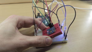
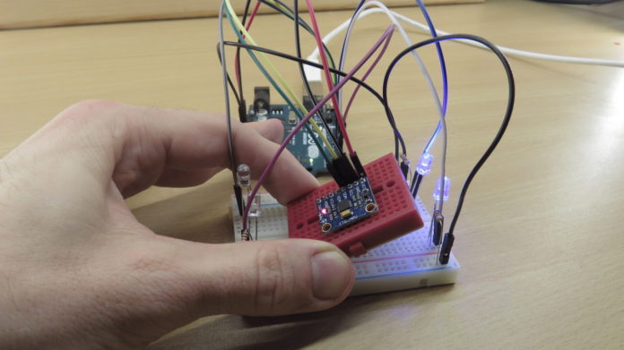
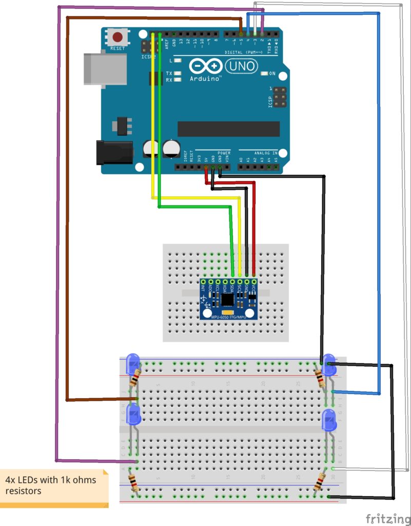
The example is very simple. Four LEDs are put in holes at the four corners of a breadboard. In the center of the breadboard is a small breadboard. The GY-521 is used to detect which side of the small breadboard is moved to the top. In order to indicate the “highest side”, two corresponding LEDs are switched on. This example is shown at around 7:15 in the video tutorial.
Wiring
Source code
// (c) Michael Schoeffler 2017, http://www.mschoeffler.de

#include "Wire.h" // This library allows you to communicate with I2C devices.

const int MPU_ADDR=0x68; // I2C address of the MPU-6050. If AD0 pin is set to HIGH, the I2C address will be 0x69.

int16_t accelerometer_x, accelerometer_y, accelerometer_z; // variables for accelerometer raw data
int16_t gyro_x, gyro_y, gyro_z; // variables for gyro raw data
int16_t temperature; // variables for temperature data

#define LED_LB 2 // LED left bottom
#define LED_RB 3 // LED right bottom
#define LED_RT 4 // LED right top
#define LED_LT 5 // LED left top

char tmp_str[7]; // temporary variable used in convert function

char* convert_int16_to_str(int16_t i) { // converts int16 to string. Moreover, resulting strings will have the same length in the debug monitor.
  sprintf(tmp_str, "%6d", i);
  return tmp_str;
}

void setup() {
  Serial.begin(9600);
  pinMode(LED_LB, OUTPUT);
  pinMode(LED_RB, OUTPUT);
  pinMode(LED_RT, OUTPUT);
  pinMode(LED_LT, OUTPUT);
  digitalWrite(LED_LB, LOW);
  digitalWrite(LED_RB, LOW);
  digitalWrite(LED_RT, LOW);
  digitalWrite(LED_LT, LOW);
  Wire.begin();
  Wire.beginTransmission(MPU_ADDR); // Begins a transmission to the I2C slave (GY-521 board)
  Wire.write(0x6B); // PWR_MGMT_1 register
  Wire.write(0); // set to zero (wakes up the MPU-6050)
  Wire.endTransmission(true);
}
void loop() {
  Wire.beginTransmission(MPU_ADDR);
  Wire.write(0x3B); // starting with register 0x3B (ACCEL_XOUT_H) [MPU-6000 and MPU-6050 Register Map and Descriptions Revision 4.2, p.40]
  Wire.endTransmission(false); // the parameter indicates that the Arduino will send a restart. As a result, the connection is kept active.
  Wire.requestFrom(MPU_ADDR, 7*2, true); // request a total of 7*2=14 registers

  // "Wire.read()<<8 | Wire.read();" means two registers are read and stored in the same variable
  accelerometer_x = Wire.read()<<8 | Wire.read(); // reading registers: 0x3B (ACCEL_XOUT_H) and 0x3C (ACCEL_XOUT_L)
  accelerometer_y = Wire.read()<<8 | Wire.read(); // reading registers: 0x3D (ACCEL_YOUT_H) and 0x3E (ACCEL_YOUT_L)
  accelerometer_z = Wire.read()<<8 | Wire.read(); // reading registers: 0x3F (ACCEL_ZOUT_H) and 0x40 (ACCEL_ZOUT_L)
  temperature = Wire.read()<<8 | Wire.read(); // reading registers: 0x41 (TEMP_OUT_H) and 0x42 (TEMP_OUT_L)
  gyro_x = Wire.read()<<8 | Wire.read(); // reading registers: 0x43 (GYRO_XOUT_H) and 0x44 (GYRO_XOUT_L)
  gyro_y = Wire.read()<<8 | Wire.read(); // reading registers: 0x45 (GYRO_YOUT_H) and 0x46 (GYRO_YOUT_L)
  gyro_z = Wire.read()<<8 | Wire.read(); // reading registers: 0x47 (GYRO_ZOUT_H) and 0x48 (GYRO_ZOUT_L)

  // print out data
  Serial.print("aX = "); Serial.print(convert_int16_to_str(accelerometer_x));
  Serial.print(" | aY = "); Serial.print(convert_int16_to_str(accelerometer_y));
  Serial.print(" | aZ = "); Serial.print(convert_int16_to_str(accelerometer_z));
  // the following equation was taken from the documentation [MPU-6000/MPU-6050 Register Map and Description, p.30]
  Serial.print(" | tmp = "); Serial.print(temperature/340.00+36.53);
  Serial.print(" | gX = "); Serial.print(convert_int16_to_str(gyro_x));
  Serial.print(" | gY = "); Serial.print(convert_int16_to_str(gyro_y));
  Serial.print(" | gZ = "); Serial.print(convert_int16_to_str(gyro_z));
  Serial.println();

  if (accelerometer_x < 1000 && accelerometer_y < -8000) {
    digitalWrite(LED_LB, HIGH);
    digitalWrite(LED_RB, HIGH);
    digitalWrite(LED_RT, LOW);
    digitalWrite(LED_LT, LOW);
  } else if (accelerometer_x < 1000 && accelerometer_y > 8000) {
    digitalWrite(LED_LB, LOW);
    digitalWrite(LED_RB, LOW);
    digitalWrite(LED_RT, HIGH);
    digitalWrite(LED_LT, HIGH);
  } else if (accelerometer_x > 8000 && accelerometer_y < 1000) {
    digitalWrite(LED_LB, LOW);
    digitalWrite(LED_RB, HIGH);
    digitalWrite(LED_RT, HIGH);
    digitalWrite(LED_LT, LOW);
  } else if (accelerometer_x < -8000 && accelerometer_y < 1000) {
    digitalWrite(LED_LB, HIGH);
    digitalWrite(LED_RB, LOW);
    digitalWrite(LED_RT, LOW);
    digitalWrite(LED_LT, HIGH);
  } else {
    digitalWrite(LED_LB, LOW);
    digitalWrite(LED_RB, LOW);
    digitalWrite(LED_RT, LOW);
    digitalWrite(LED_LT, LOW);
  }

  // delay
  delay(10);
}

Hi, I am a high school student competing in the science fair and I was wondering if it was okay to use your source code. Obviously, I will make proper citations. I am just not sure since you have included the “// (c) Michael Schoeffler 2017, http://www.mschoeffler.de“
Yes, of course!
I tested your code. Unfortunately I get the value -1 for everything (except temperature, here I get 36.53). Any idea what could have happened? I copied the code, so there shouldn’t be a typo in the code.
Hi
I am a newbie. And working on a water rocket project and I just wanted to ask how to make the gy-5-21 more critical? So for example, the LEDs turns on then the breadboard has rotated something like 180 degrees.
Best regards
Aleksander
Always Great Project,is there any change on that code needed for Arduino Due?
Excellent
Hello, this code is close to my project but in a way im trying to change using the LED to a vibrator motor. What changes in the code should be changed?