
This tutorial gives an introduction to the HY-M154 / 817 optocoupler module. Moreover, a simple application is programmed that shows how to wire and how to program an Arduino when working with the module. In this tutorial, the module is used as an “digital input board”. If you want to use the module as “digital output board”, have a look at cmheong’s article.
Related products
HY-M154 / 817 / PC817 Optocoupler Module
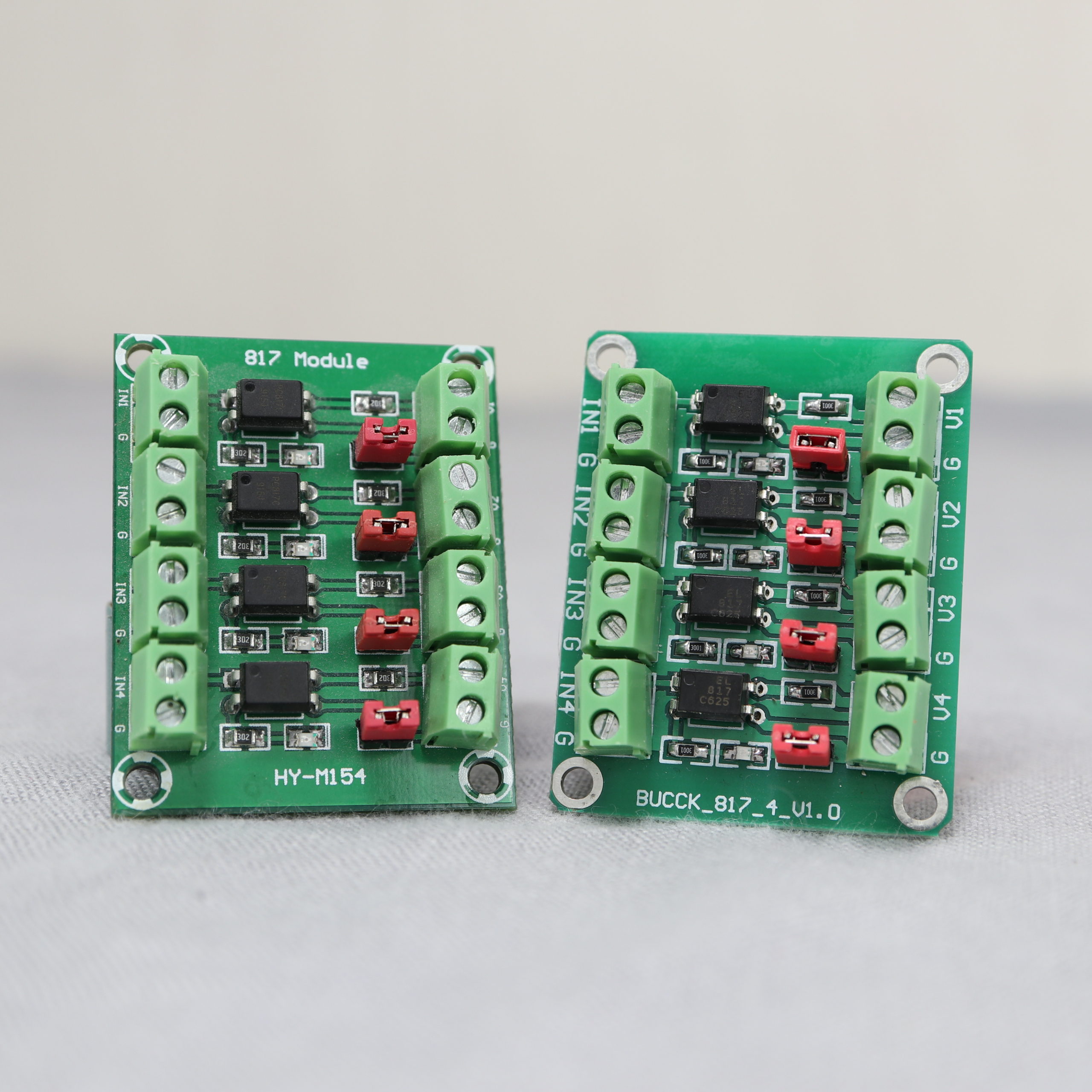
The HY-M154 module is a 4-channel optocoupler board. You can find the same board under different names. I have another board which is named BUCCK_817_4_V1.0. So, don’t worry if your board has a different name.
The main functionality of the HY-M154 module is to convert an input signal from one voltage level into another voltage level. For example, the module is useful, if you have a 9V input signal that you want to read with a 5V- (Arduino Uno,…) or 3.3V-compatible device (ESP32, Raspberry Pi GPIO).
The four channels are fully isolated to each other. So it’s possible to handle four different input voltage signals and four different output voltage signals. For each channel, the conversion is performed by an SMD optocoupler of type PC817. Moreover, each channel has a jumper. If the jumper is set, the GND of the input and output signal are connected. If you need fully isolated input and output signals, you must remove the jumper. Furthermore, the board has an LED for each channel. If the LED is switched on, the input signal delivers a “HIGH” signal.
Specification
| Name | Value |
|---|---|
| Input signal voltage | 3.6V-24V |
| Output signal voltage | 3.6V-30V |
| Frequency limit | 4 kHz |
If you are interested in more information about the PC817C optocoupler SMD, look for the official datasheet (Manufacturer: Sharp).
Example application: Arduino Uno & HY-M154
The idea is to have a circuit with a voltage level of 12V. We want to check whether the 12V circuit is switched on. If so, the Arduino Uno prints out the message “Circuit is switched on”. If not, the Arduino print “Circuit is switched off”. Since the Arduino pins expect a voltage level of 5V, we use the HY-M154 board to convert the 12V signal to a 5V signal. The 5V signal is read by the Arduino Uno.
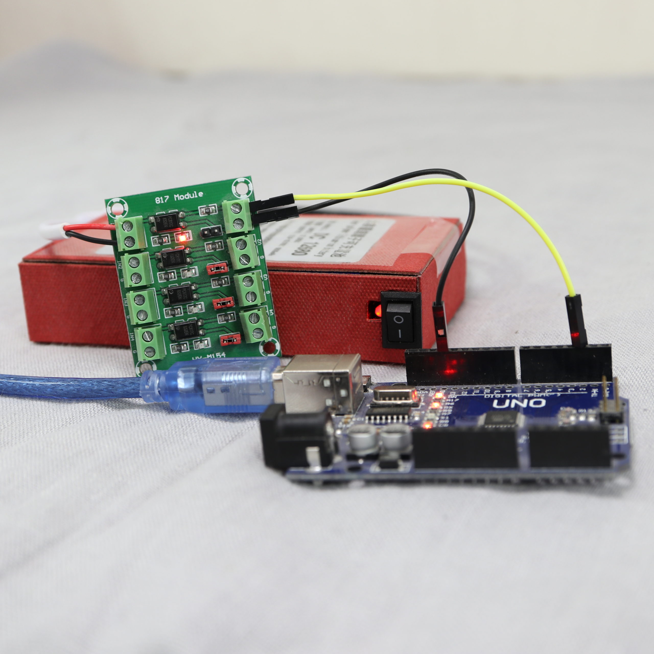
For the 12V circuit a 12V battery pack and DC power jack (female) adapter is used.
Wiring
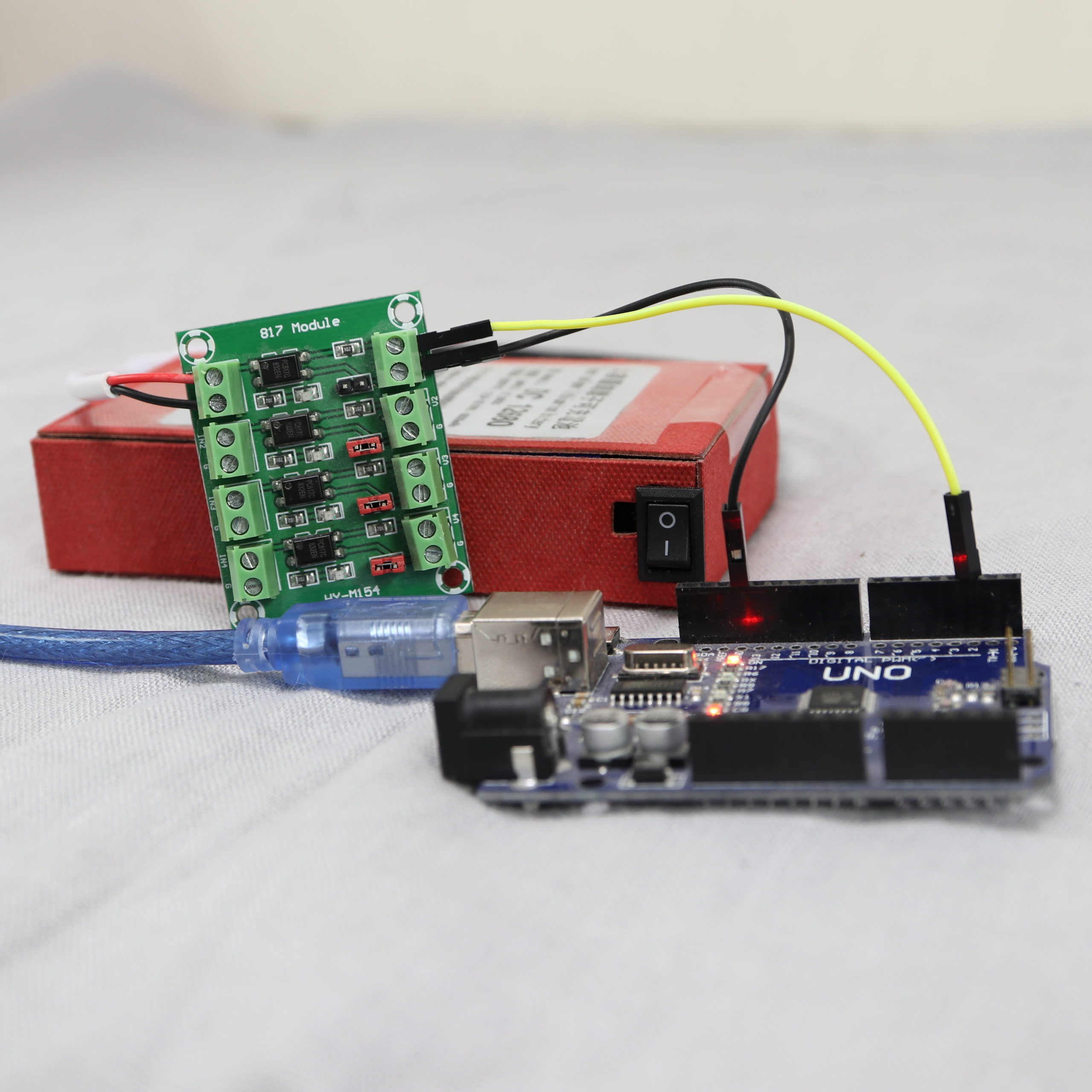
For the example application, only four connections have to be wired. The HY-M15’s output terminal blocks V1 and G are wired to Pin 2 and GND of the Arduino. The input terminal blocks IN1 and G are wired to the battery/DC adapter’s +12V and GND wire. I keep both circuits fully isolated to each other. Therefore, the jumper is removed.
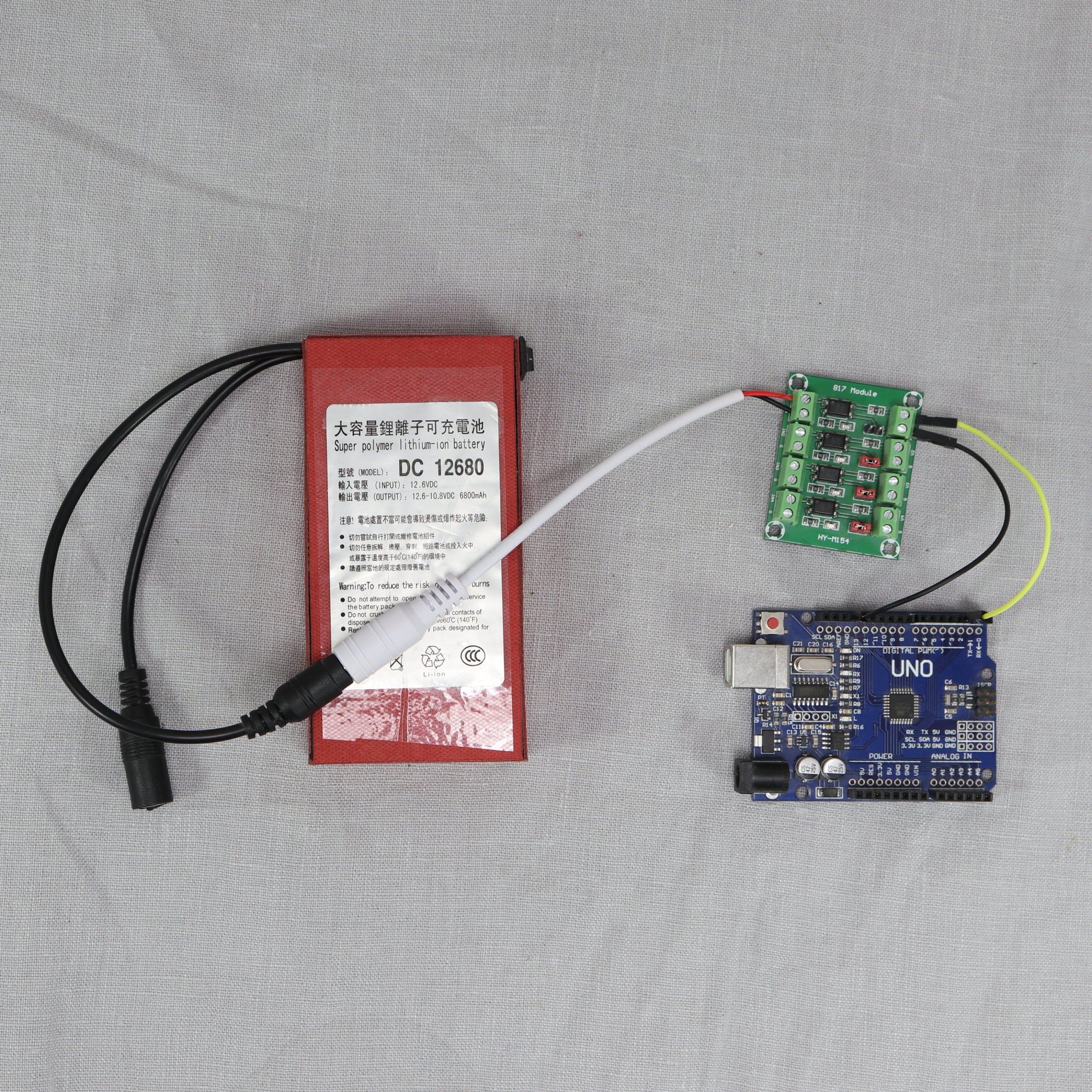
The following table gives an overview of all connections:
| Wire / Color | HY-M154 Board Pin | Arduino Uno Pin | Battery/DC adapter |
|---|---|---|---|
| #1 / Yellow | V1 | Digital Pin 2 | |
| #2 / Black | G | GND | |
| #3 / Red | IN1 | +12V wire (red) | |
| #4 / Black | G | GND wire (black |
Programming
The use of the HY-M154 module is very simple. In order to detect the circuit state (on/off), it’s sufficient to manage a single pin.
In the setup function, the digital pin 2 is set to INPUT_PULLUP mode. INPUT_PULLUP means, the pin’s signal is HIGH, if there is no connection to the GND pin (circuit switched off). If the optocoupler triggers due to a switched on 12V circuit, the signal of pin 2 is LOW. Besides setting the pin mode, the serial connection is started.
In the loop function, the current state of digital pin 2 is read. If the pin state is HIGH, a message (“Circuit is switched off!”) is printed to the serial connection. If the pin state is LOW, the circuit must be switched on and therefore the message “Circuit is switched on!” is printed. At the end, a delay of one second is added to avoid spamming the serial monitor.
/*
MIT License
Copyright 2021 Michael Schoeffler (https://www.mschoeffler.com)
Permission is hereby granted, free of charge, to any person obtaining a copy of this software and associated documentation files (the "Software"), to deal in the Software without restriction, including without limitation the rights to use, copy, modify, merge, publish, distribute, sublicense, and/or sell copies of the Software, and to permit persons to whom the Software is furnished to do so, subject to the following conditions:
The above copyright notice and this permission notice shall be included in all copies or substantial portions of the Software.
THE SOFTWARE IS PROVIDED "AS IS", WITHOUT WARRANTY OF ANY KIND, EXPRESS OR IMPLIED, INCLUDING BUT NOT LIMITED TO THE WARRANTIES OF MERCHANTABILITY, FITNESS FOR A PARTICULAR PURPOSE AND NONINFRINGEMENT. IN NO EVENT SHALL THE AUTHORS OR COPYRIGHT HOLDERS BE LIABLE FOR ANY CLAIM, DAMAGES OR OTHER LIABILITY, WHETHER IN AN ACTION OF CONTRACT, TORT OR OTHERWISE, ARISING FROM, OUT OF OR IN CONNECTION WITH THE SOFTWARE OR THE USE OR OTHER DEALINGS IN THE SOFTWARE.
*/
/*
* This is an example program that is part of an Arduino tutorial about the HY-M154 / 817 / PC817 Optocoupler Module.
* The idea is to detect whether a circuit (12V) is switched on or off.
*/
#define PIN_VOLTAGE_READ 2 // Digital pin 2 is wired to IN1 of the HY-M154
void setup() {
pinMode(PIN_VOLTAGE_READ, INPUT_PULLUP); // Input pullup means that the signal is HIGH if circuit is switched off!
Serial.begin(9600); // Init serial connection
}
void loop() {
bool state = digitalRead(PIN_VOLTAGE_READ); // read state of the circuit
if (state) {
Serial.println("Circuit is switched off!"); // HIGH state corresponds to switched off, due to the use of INPUT_PULLUP
} else {
Serial.println("Circuit is switched on!");
}
delay(1000); // wait for one second
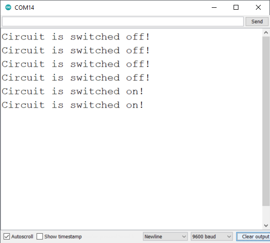
}If the program is transferred to the Arduino, the first messages should appear on the serial monitor. In my case, I started the Arduino when the circuit was switched off.
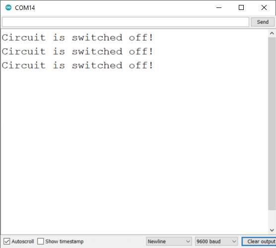
If the circuit is switched on, the corresponding message “…switched on!” should appear on the serial monitor.
Conclusion
The HY-M154 is a cheap and easy-to-use board when it comes to reading digital signals with voltage levels that are not supported by the used microcontroller. If you are looking for such a module, you can also go with a module named “817” or “PC817” etc. In my experience, they are basically the same module type as the HY-M154 that was used in this tutorial.
The 817s are ideally suited for triggering cameras and flash units. However, I found it to be sensitive components. Several arrived in a non-working state (as components) and the boards, while once functional, gave out in later tries. It must be very easy to damage them though I haven’t yet found out how.
IS this working in Jetson nano please explain about it
i have the same board. but the led of the input side (In – G) comes red as soon as I put in the +12v wire and nothing else. the jumper is out. what’s happening ? thanks.
I know this is an old post. I am curious why this works on an Arduino and not on an ESP32. Most of your tutorials work for either and this one does not?