
Recently, Seeed Studio published a new “starter kit”, the so-called Arduino Sensor Kit. In this article, I want to give a short overview to the new kit. Moreover, I want to compare it to the Grove Beginner Kit that I reviewed a few month ago, since both kits look very much alike. I will check whether my example project from the last article does also work for the Arduino Sensor Kit. Finally, I want to elaborate on whether it can also be used with an ESP32 instead of an Arduino. This would be beneficial e.g. for beginners, who plan to start with an Arduino but then would like to go on with an ESP32. For example to work on wireless applications.
Related products
Arduino Sensor Kit
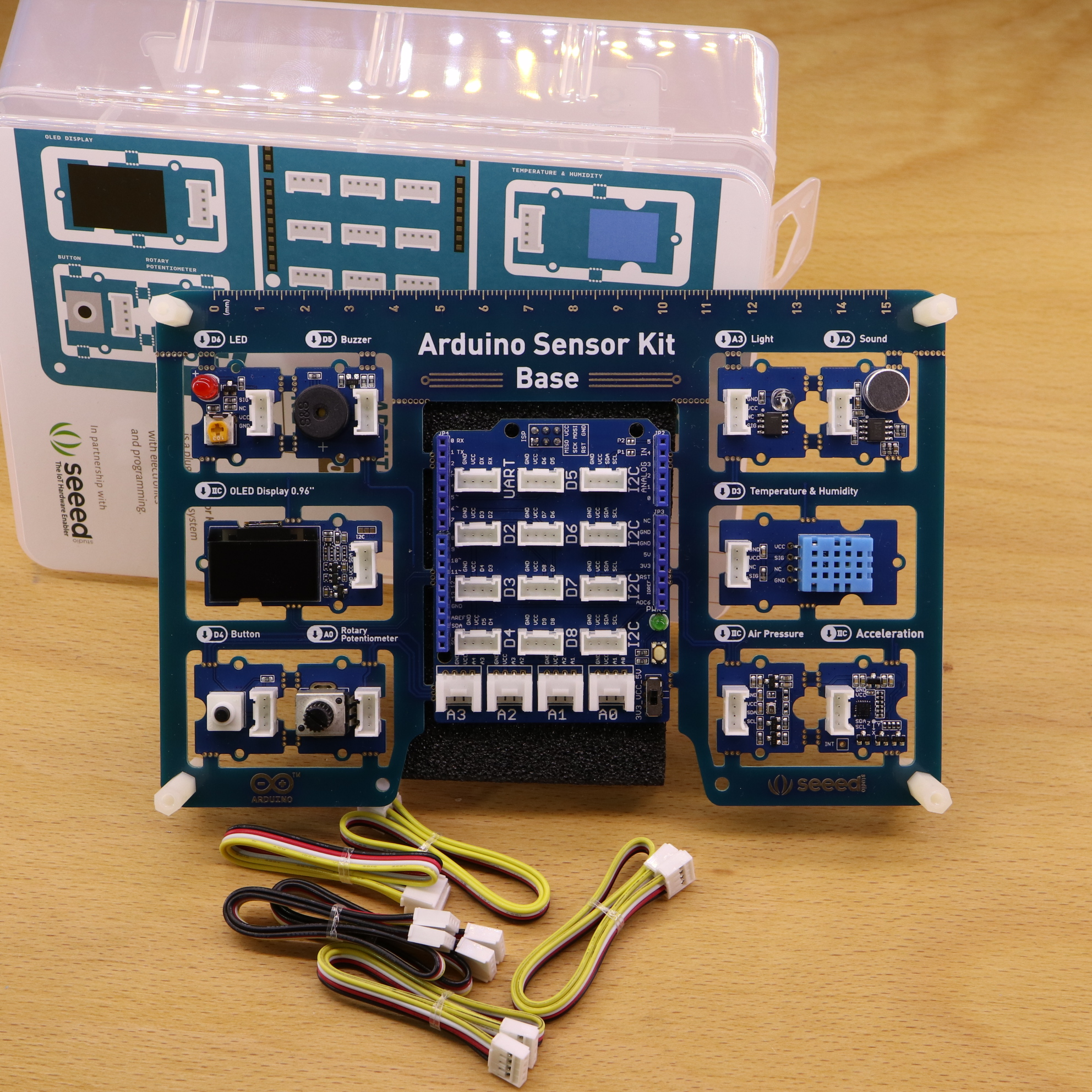
The Arduino Sensor Kit is a large printed circuit board (PCB) that comes with 10 integrated (sensor) modules. The idea is to mount the board on top of an Arduino Uno (not included). In addition to the modules, the board has an integrated ‘Grove Base Shield’. The Arduino becomes then compatible to the Grove ecosystem.
Similar to the Grove Beginner Kit, the Arduino Sensor Kit addresses people that are looking for an easy start into the Arduino ecosystem—without putting a lot of effort into wiring modules. Due to the cooperation with Arduino (arduino.cc), you find a full tutorial on their website.
The modules are ‘PCB-wired’ to the Grove Base Shield. That means, you can leave them as they are or, alternatively, break-them out from the board. When you broke them out, you have to connect them by Grove cables (included) to the Grove Base Shield to make them work again.
Example Project: Light Intensity Alarm — Does it still work?
For my previous article about the Grove Beginner Kit, I added a new example project in which an LED and Buzzer has been controlled based on how much light is detected by the Light sensor. When I got my hands on the Arduino Sensor Kit, I immediately tried to compile my example for the Arduino Sensor Kit. Unfortunately, it did not work out of the box. I realized that the Arduino Sensor Kit comes with some changes at the pin layout (addressed in next section). Therefore, I changed my example in order to make it work for the Arduino Sensor Kit:
/*
MIT License
Copyright 2020 Michael Schoeffler (https://www.mschoeffler.de)
Permission is hereby granted, free of charge, to any person obtaining a copy of this software and associated documentation files (the "Software"), to deal in the Software without restriction, including without limitation the rights to use, copy, modify, merge, publish, distribute, sublicense, and/or sell copies of the Software, and to permit persons to whom the Software is furnished to do so, subject to the following conditions:
The above copyright notice and this permission notice shall be included in all copies or substantial portions of the Software.
THE SOFTWARE IS PROVIDED "AS IS", WITHOUT WARRANTY OF ANY KIND, EXPRESS OR IMPLIED, INCLUDING BUT NOT LIMITED TO THE WARRANTIES OF MERCHANTABILITY, FITNESS FOR A PARTICULAR PURPOSE AND NONINFRINGEMENT. IN NO EVENT SHALL THE AUTHORS OR COPYRIGHT HOLDERS BE LIABLE FOR ANY CLAIM, DAMAGES OR OTHER LIABILITY, WHETHER IN AN ACTION OF CONTRACT, TORT OR OTHERWISE, ARISING FROM, OUT OF OR IN CONNECTION WITH THE SOFTWARE OR THE USE OR OTHER DEALINGS IN THE SOFTWARE.
*/
/*
Explanation: The idea of this example is to control the LED and Buzzer based on how much light is detected by the Light sensor.
The higher the amount of light, the higher the frequency of the LED blinking and the Buzzer turning on.
Moreover, the Buzzer is only active if the Button is pressed.
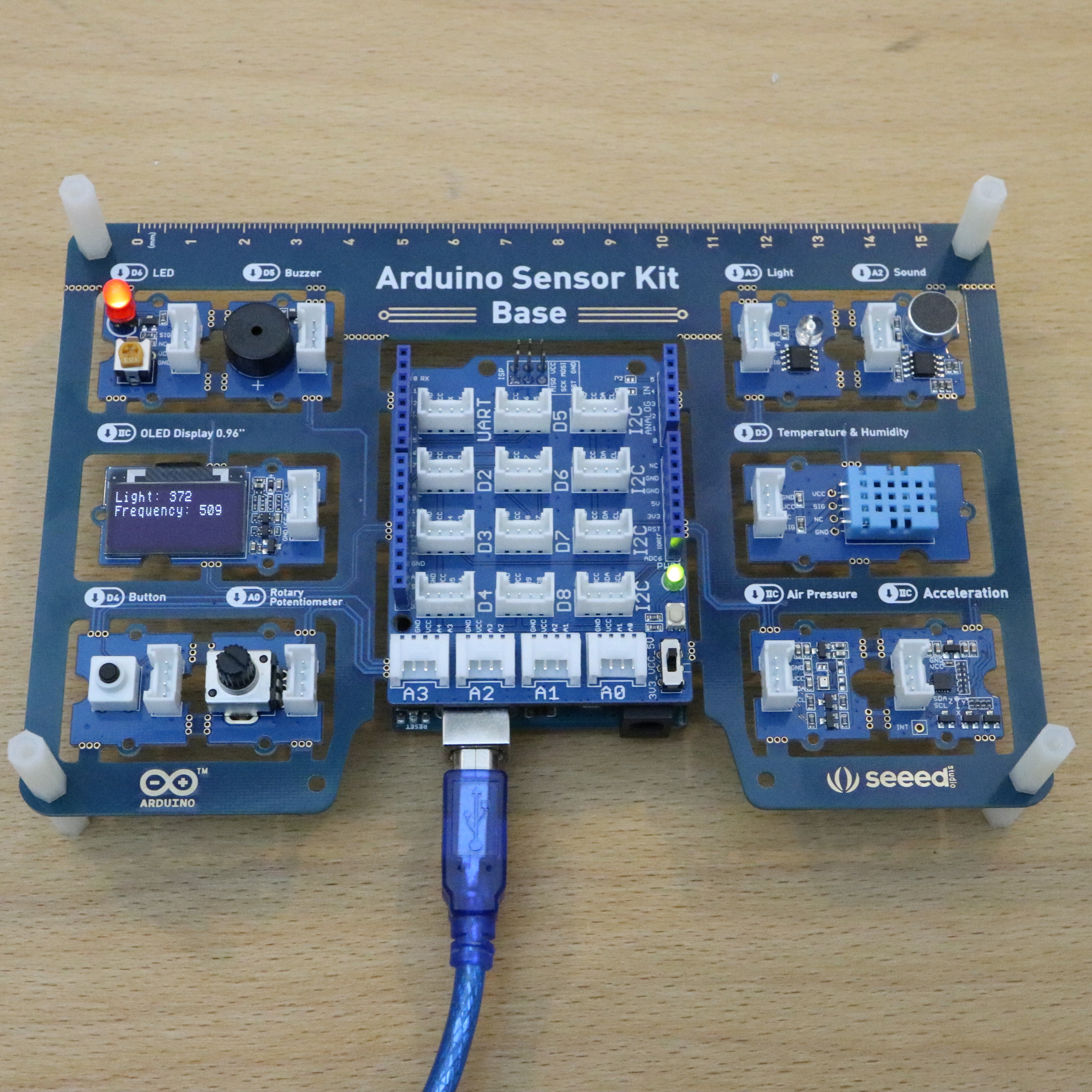
The OLED display shows the currently detected light and the corresponding frequency used for LED and Buzzer.
-- ADAPTED TO ARDUINO SENSOR KIT (ORIGINALLY MADE FOR GROVE BEGINNER KIT) --
*/
#include <U8x8lib.h> // Header file is part of the required U8g2 library. Arduino IDE: Install U8g2 library --> Go to "Tools", then "Manage Libraries.".
#define LED 6 // LED is on Digital Pin 6 (Grove Beginner Kit: 4)
#define Buzzer 5 // Buzzer is on Digital Pin 5
#define Button 4 // Button is on Digital Pin 4 (Grove Beginner Kit: 6)
#define Light A3 // Light sensor is on Analog Pin 4 (Grove Beginner Kit: Analog pin 6)
U8X8_SSD1306_128X64_ALT0_HW_I2C u8x8(/* reset=*/ U8X8_PIN_NONE); // Part of the initialization of the OLED Display 0.96"
bool toggle = false; // This variable represents the toggle state of the LED and Buzzer
void setup() {
pinMode(LED, OUTPUT); // LED is an output
digitalWrite(LED, LOW); // LED is set to zero --> "out"
pinMode(Buzzer, OUTPUT); // Buzzer is also an output
digitalWrite(LED, LOW); // Buzzer is set to zero --> "out"
pinMode(Button, INPUT); // Button is an input
pinMode(Light, INPUT); // Light sensor is also an input
u8x8.begin(); // Display is now ready to use
u8x8.setFlipMode(1); // Technically, the display is mounted upside down on the Grove module. Therefore, we flip it.
u8x8.setFont(u8x8_font_chroma48medium8_r); // font type
}
void loop() {
int light_measured = analogRead(Light); // Light is measured
int frequency = map(light_measured, 0, 750, 1000, 10); // Amount of light is converted to the turn on/off frequency of the LED (and buzzer).
// Additional explanation: No light (sensor value: 0) will switch on/off the LED each 1000ms
// A lot of light (sensor value => 750) will switch on/off the LED each 10ms ("LED starts flickering")
u8x8.clear(); // Display is cleared in each step to remove old values
u8x8.setCursor(0, 0); // Cursor of display is set to first position (first row)
String light = "Light: " + String(light_measured); // String with measured light value
u8x8.print(light.c_str()); // string is printed to display
u8x8.setCursor(0, 1); // Cursor is set to the second row
String freq = "Frequency: " + String(frequency);
u8x8.print(freq.c_str());
digitalWrite(LED, toggle); // The LED is turned on/off based on the current value of the toggle variable
if (digitalRead(Button) == HIGH) { // if the button is pressed, some additional code is executed (Buzzer)
digitalWrite(Buzzer, toggle); // Buzzer get's also a toggle value. This will result in a short audible 'click' (synchronized with the LED status)
}
toggle = !toggle; // Toggle value is inverted; E.g. if toggle is LOW, the new value will be HIGH.
delay(frequency); // The code is executed again after a waiting time that corresponds to the calculated frequency representation.
// Additional remark: The previous line is a minor weakness of the code, if the amount of light/frequency is low, the reaction time of the programm is also low as it is in 'delay' state
}With the changes made for the pin definitions, the example does also run on the Arduino Sensor Kit.
Comparison of Arduino Sensor Kit and Grove Beginner Kit
Next, we have a look at the differences between Arduino Sensor Kit and Grove Beginner Kit. Here is the most obvious one:
- The Grove Beginner Kit comes with an Seeeduino Lotus, which is a fully Arduino-compatible Microcontroller board.
- The Arduino Sensor Kit does not come with a microcontroller. Instead, it has a shield that has to be put on top of an Arduino.
Moreover, Seeed Studio changed some pins:
| Module | Pin – Grove Beginner Kit | Pin – Arduino Sensor Kit |
|---|---|---|
| LED | D4 | D6 |
| Button | D6 | D4 |
| Light Sensor | A3 | A6 |
Fun fact, exactly the pins that I used in my Light Intensity Example have been changed. The other modules have the same pins for both Kits. Besides that, there are only minor changes. Seeed published a document that shows the changes in more detail (Link). In general, the change of the pins is not a big issue. I guess, the normal customer decides on either the Arduino- or Grove variant and won’t buy both boards. Moreover, except for the pin changes, the boards are very compatible to each other.
Is the Arduino Sensor Kit also usable for ESP32?
The Arduino is around for almost 10 years by now — and still a very popular platform to get started with electronics. Within the last years, also the ESP8266 and ESP32 got a lot of attention. My impression is that a lot of people start also with ESP8266/ESP32-based microcontroller, e.g. when they are looking for wireless applications right from the start.
I asked myself, what if you are looking for a good starter kit, e.g. for the Arduino Uno that you want to re-use for the ESP32. So I took my ESP32 DEVKIT (V1) and started to try it out. As
Please note, the re-use for ESP32 requires some wiring. So the initial idea of “no wiring required” can’t be adapted to the ESP32 use case.
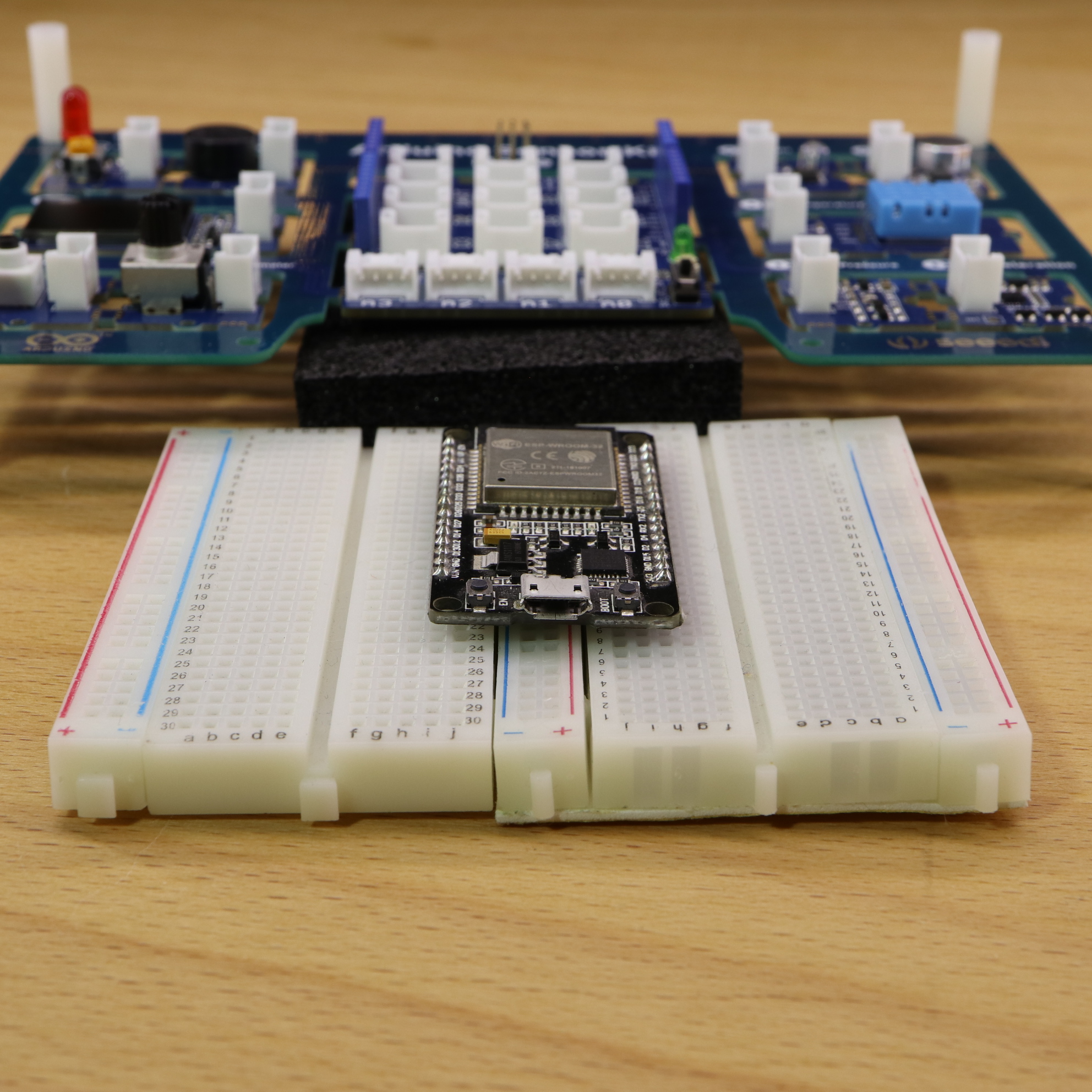
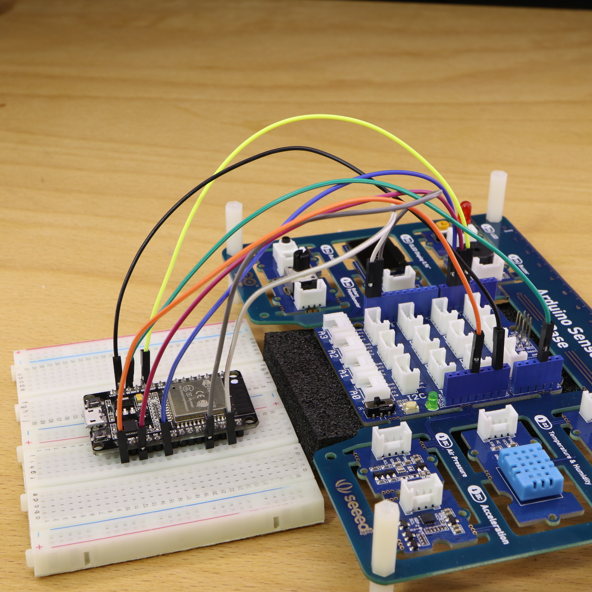
First, we have to make sure that the pins of the Arduino Sensor Kit do not take any damage. This can be done by using the piece of foam that was already included (for packaging reasons). Then, we have to connect, the ESP32 to the Arduino Sensor Kit. Btw. when I do wiring work with an ESP32, I use two breadboards as a single breadboard is not wide enough for the ESP32:
Unfortunately, we cannot use the same pins in the Arduino programming when running on an ESP32, since the ESP32 has a different pin layout (and numbering). For the wiring, just wire the ESP32 pins to the upper (female) pins of the Grove Base Shield. The following table shows the wiring changes:
| Module | ESP32 | Pin – Arduino Sensor Kit |
|---|---|---|
| LED | 16 | D6 |
| Button | 14 | D4 |
| Light Sensor | 13 | A6 |
| Buzzer | 15 | D5 |
| OLED Display (IIC) | 22 | SCL |
| OLED Display (IIC) | 21 | SDA |
| – | GND | GND |
| – | 3.3V | 3.3V |
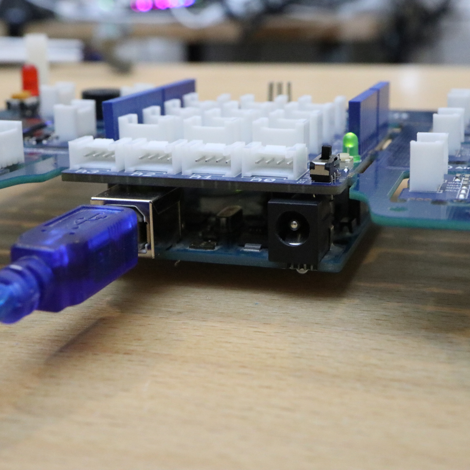
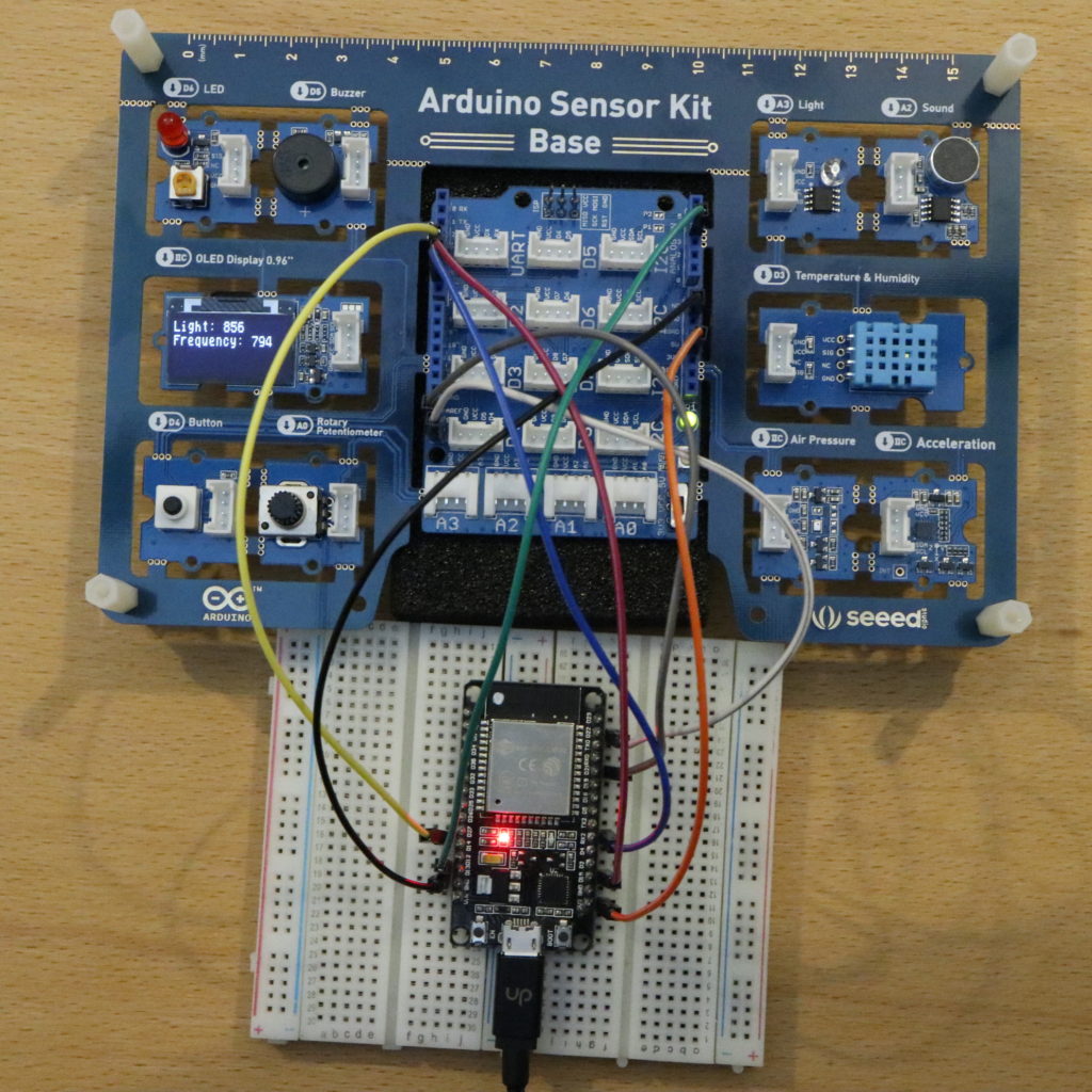
Then, I switched the little switch of the Grive Base Shield from 5V to 3.3V (bottom right corner).
This is how my wiring looks like.
The new pin layout results in some code changes. Moreover, there is another code change. The analog values of an ESP32, result in a value between 0 and 4095 — instead of 0 and 1023 (Arduino Uno). Therefore, the parameter of the map function has to be changed ( at the beginning of the loop function). Btw. I changed the data types of two variables from int to unsigned. It is not crucial. However, I thought it is the “better” choice since the variables must not become negative (results in an endless delay at the end). So, here is the updated code:
//...
#define LED 16 // LED is on Digital Pin 16 (Arduino Sensor Kit Kit: D6)
#define Buzzer 15 // Buzzer is on Digital Pin 15 (Arduino Sensor Kit Kit: D5)
#define Button 14 // Button is on Digital Pin 14 (Arduino Sensor Kit Kit: D4)
#define Light 13 // Light sensor is on Analog Pin 13 (Arduino Sensor Kit Kit: A3)
//...
void loop() {
  unsigned light_measured = analogRead(Light); // Light is measured
  unsigned frequency = map(light_measured, 0, 4095, 1000, 10); // Amount of light is converted to the turn on/off frequency of the LED (and buzzer).
  // Additional explanation: No light (sensor value: 0) will switch on/off the LED each 1000ms
  // A lot of light (sensor value => 4095) will  switch on/off the LED each 10ms ("LED starts flickering")
//...
If you performed all steps correctly, also the ESP32 should be able to run the program on the Arduino Sensor Kit. Due to the use of 3.3V, the buzzer is not as loud as before. Besides that, everything else should work as expected.
Summary
The Arduino Sensor Kit is a well designed board for beginners that want to try out a lot of different sensor modules — without the need for wiring. An advantage is that you are free to choice whether you want to go on with the Grove ecosystem or stick with the Arduino ecosystem. Moreover, I have shown that it’s also possible to use the board together with an ESP32. This is helpful if someone wants to go on with wireless applications.
If you want to find out more about the Arduino Sensor Kit, have also a look at the official page.
Video Tutorial
hi Michael
this is good comparison review.
I only have a few notes for you:
– the Arduino UNO form factor has been around since approximately 2005
– the Arduino UNO WiFi Rev 2 is fully compatible and provides WiFi+BLE connectivity
– you should not run your examples with the anti-static foam attached to the board. The foam is conductive and might ruin your electronics and/or create short-circuits
Hi Ubi,
thanks for the very good comment!
About your comment with the anti-static foam: My first thought was “ok shit, I totally forgot about the anti-static property”. I immediately tested the foam with a multimeter. To my surprise, the multimeter did not show any continuity. So, either my measurements were not correct or the foam is indeed not anti-static. Nonetheless, I will take more care in the future. Thanks!
Hi
I just wanna ask incase if we want to use 2 I2C components on ARDUINO sensor base shield like reading air pressure and showing on OLED, how would that be possible.
your help would be appreciated..
Thanks
I loved the idea of connecting an ESP32 to this kit while keeping the sensors intact. Thanks for sharing, Michael ? Do you think I could do a similar ESP32 setup with the my “Grove Beginner Kit” without damaging the Seeeduino Lotus board?