
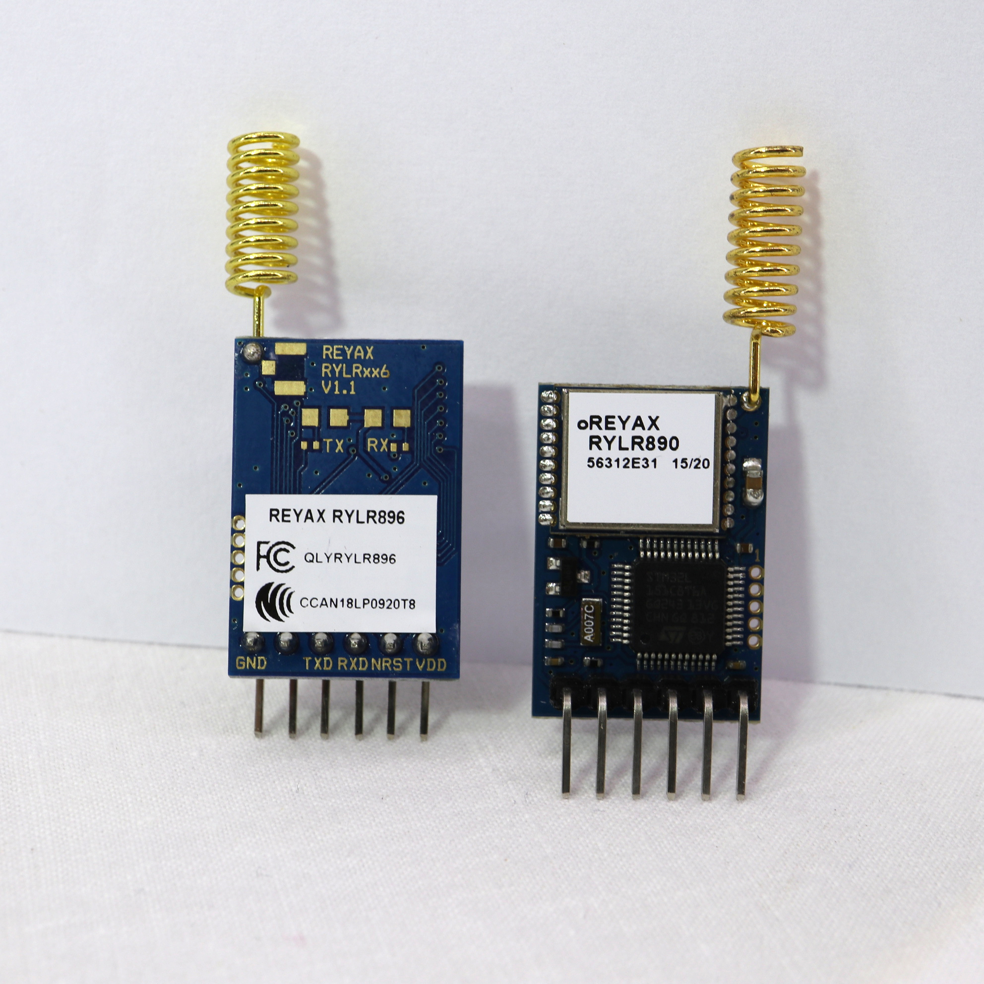
This tutorial teaches how to use two RYLR896 breakout boards in order to implement a simple sender-to-receiver communication with LoRa. LoRa stands for “Long Range” and is a wireless radio frequency (RF) technology that is well suited for long communication distance and low power scenarios. LoRa uses license-free sub-gigahertz radio frequency bands for communication. The radio frequency differs from region to region. In Germany, LoRa is used with a center frequency of 868 MHz (Europe). Example frequency of other regions are: 865 MHz to 867 MHz (India), 915 MHz (Australia and North America), and 923 MHz (Asia). The RYLR896 is a breakout board that comes with an RYLR890 LoRa Module (Semtech SX1276 Engine). In this tutorial, we use two RYLR896 breakout boards to establish a communication between them.
Related products
REYAX RYLR896 Breakout Board / RYLR890 Module
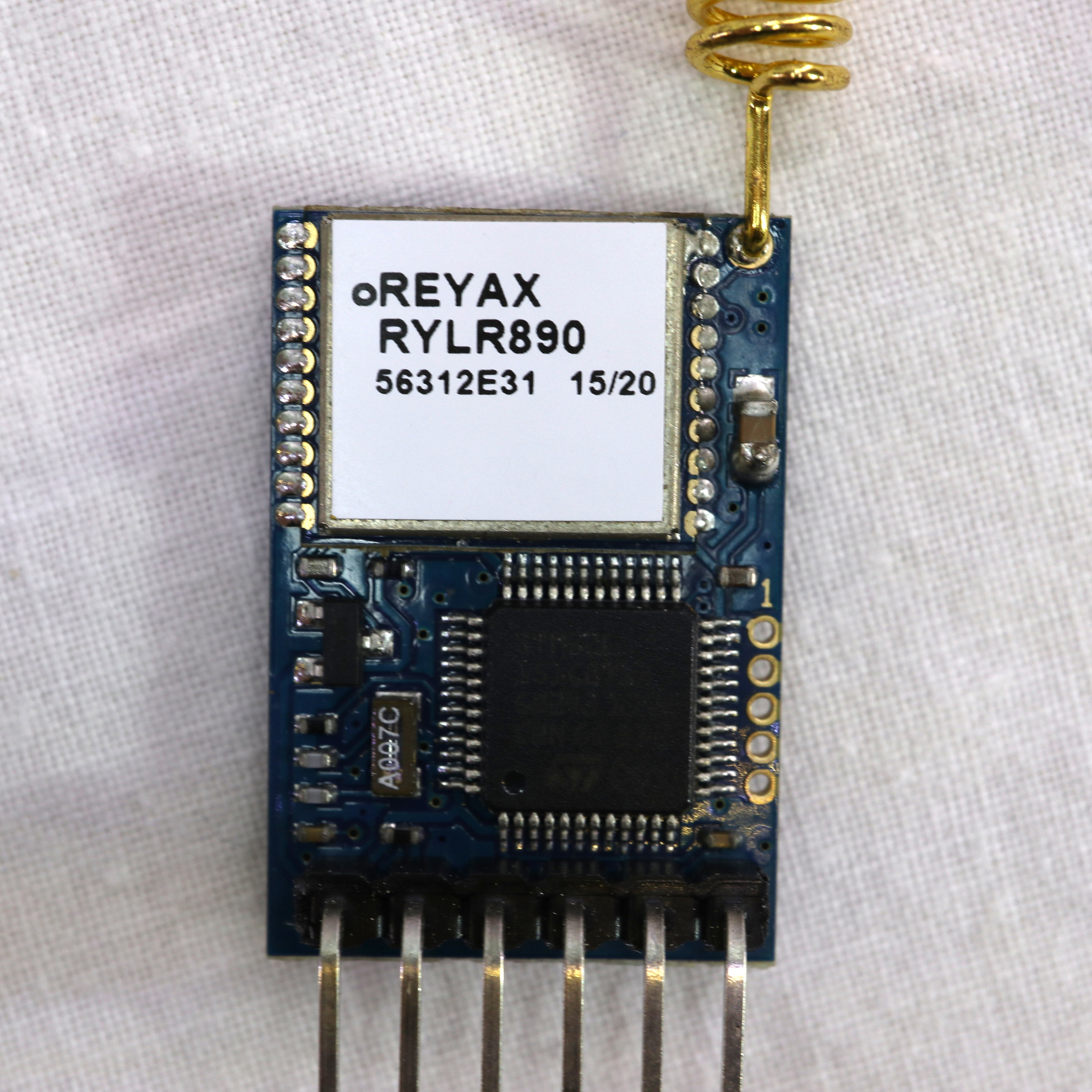
Don’t get confused: RYLR896 is the breakout board incl. pins, a STM32L microcontroller IC, antenna, and an RYLR890 module. The RYLR890 module is based on the Semtech SX1276 LoRa Engine and contains all the “LoRa logic”. According to REYAX, the module is supposed to achieve a typical communication distance of 4.5 km. Naturally, the communication distance depends on many aspects. Nonetheless, 4.5 km should be achievable under normal conditions (e.g. clear line-of-sight). The following table shows some characteristics of the RYLR890 module:
| Item | Min | Typical | Max |
|---|---|---|---|
| Power Supply Voltage | 2.8 V | 3.3 V | 3.6 V |
| Frequency Range | 820 MHz | 868/915MHz | 1020 MHz |
| Communication Range | 4.5 km | 15 km | |
| Transmit Current | 43 mA | ||
| Receive Current | 16.5 mA |
The RYLR896 breakout board makes the use of the RYLR890 very easy. For instance, the breakout board comes with an own IC and pins, so it is ready to use for controlling it by a serial connection. The pin layout is quite easy, you require only to connect four pins to the RYLR896 to be able to control the RYLR890 module:
| Name | Input/OUTPUT | Description |
|---|---|---|
| VDD | Input | Power Supply |
| NRST | Input | Active-Low Reset (optional) |
| RXD | Input | UART Data Input |
| TXD | Output | UART Data Output |
| NC | – | |
| GND | – | Ground |
Controlling a RYLR896/RYLR890 module by a serial connection
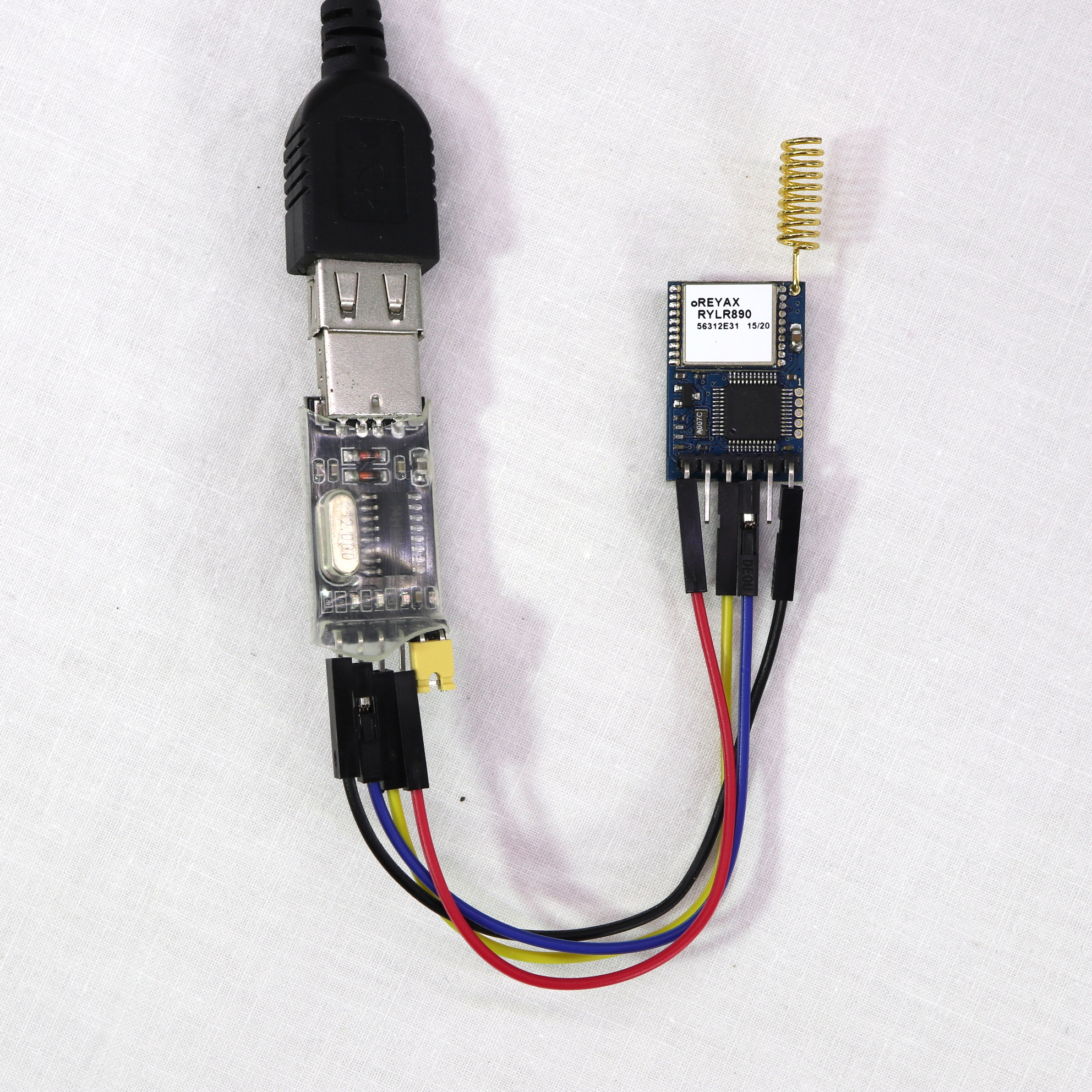
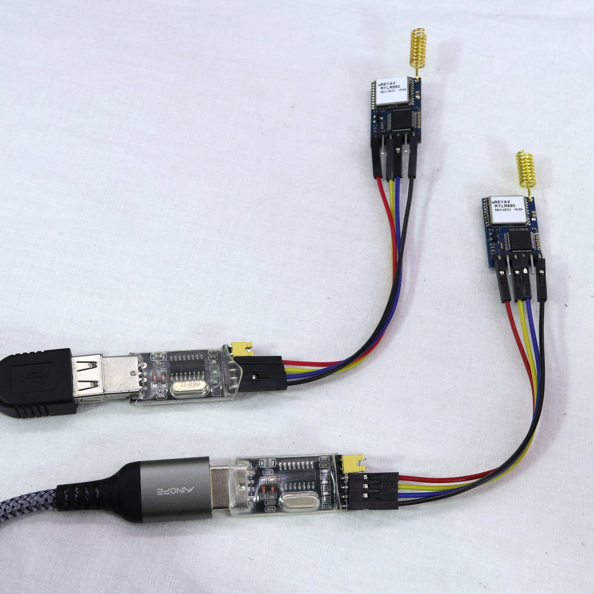
First, we establish a serial connection to be able to control an RYLR890 module, e.g. to have a look in some module settings. As in my other tutorials about Reyax modules ( RYWB116, RYBI080, and RYS8830), a “USB-to-TTL” device is used to establish a connection between a PC and the breakout board. It is important that the USB-to-TTL device has a 3.3V mode. For my device, in order to activate the 3.3V mode (and deactivate 5V mode) a jumper has to be set.
| USB-to-TTL Pin | RYLR896 Pin |
|---|---|
| 5V | no connection / yellow jumper with USB-TO-TTL VCC |
| VCC | no connection / yellow jumper with USB-TO-TTL 5V |
| 3V3 | VDD |
| TXD | RXD |
| RXD | TXD |
| GND | GND |
Next, we can use a terminal program to send and receive data to the module. There are many terminal programs available. I chose the free program HTerm from Tobias Hammer. HTerm has all functions that we need to exchange data with the RYLR896 breakout board. But of course, you can use any other terminal program for this task. On the next screenshot, you see my configuration parameters for the serial connection (Port: depends on setup, Baud rate: 115200, Data: 8, Stop: 1, Parity: None, Receive Newline: CR+LF, Transmit Command Delimiter: CR+LF):
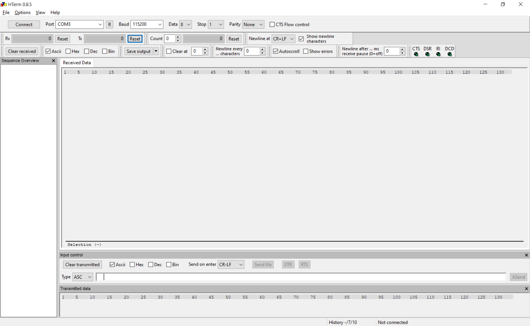
After starting the serial connection, we can test the communication with a simple “AT” command. The Module should respond with an OK:
< AT\r\n
> +OK\r\n
Next, let’s check some settings of the module: the module’s version and band/center frequency. This can be done by the commands “AT+VER?\r\n” and “AT+BAND?”:
< AT+VER?\r\n
> +VER=RYLR89C_V1.2.7\r\n
< AT+BAND?\r\n
> +BAND=915000000\r\n
According to the response, the band is set to the frequency of North America (915 MHz). Since I live in Europe, I want to change it to 868 MHz. This can be achieved by the following command:
< AT+BAND=868500000\r\n
> +OK\r\n
In order to establish a communication between two modules, they must be able to find each other by an address. The addressing scheme of the LoRa ecosystem depends a bit on the modules and implementation. Simply spoken, the module enables us to set a network id and an address. Modules on the same network can communicate with each other. Each module is supposed to have a unique id within a network. In this tutorial, we set the network id to 5 and the address to 101:
< AT+NETWORKID=5\r\n
> +OK\r\n
< AT+ADDRESS=101\r\n
> +OK\r\n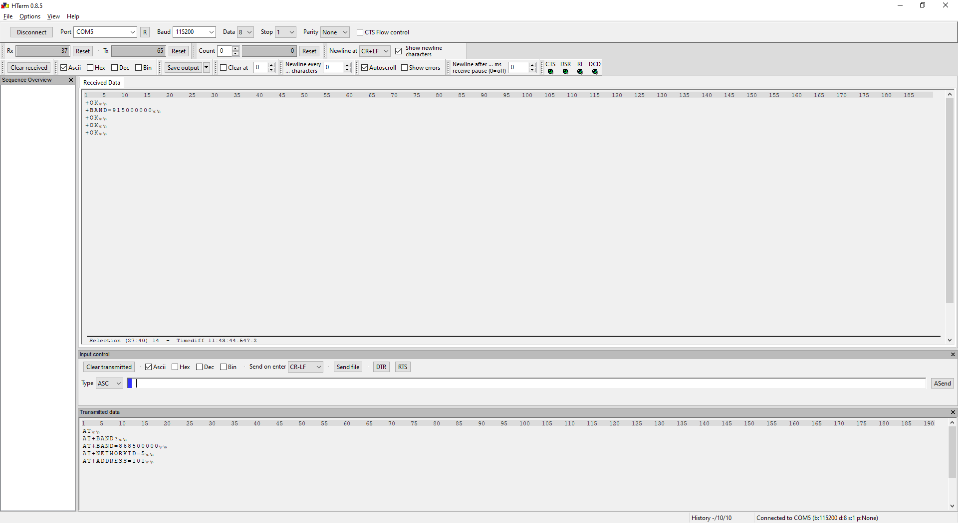
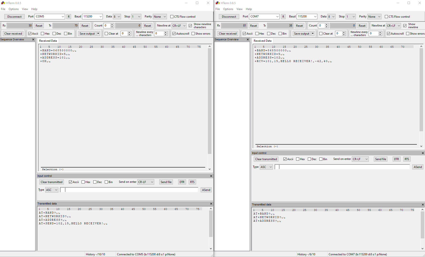
Now, the module is set to the correct frequency, network id and address. I will apply the same settings to a my second module. For the second module, the address is set to 102.
Sender/Receiver Communication with two RYLR890 modules
If both modules are correctly configured, to establish a communication is very easy. Here, I used two USB-to-TTL devices to have them both connected to my PC in order to send a message with the first module and, at the same time, be able to monitor incoming messages of the second module.
In order to send a message, just send the command “AT+SEND=102,15,HELLO RECEIVER!” at the serial connection of the first module. The first parameter value ‘102’ is the address of the second module. The next value ’15’ is the number of characters/bytes to be send. The third parameter value is the message to be send: ‘HELLO RECEIVER!’ (15 characters).
< AT+SEND=102,15,HELLO RECEIVER!\r\n
> +OK\r\n
The second module should be able to receive the message after a very short moment. The received message will be automatically printed into the serial connection:
> +RCV=101,15,HELLO RECEIVER!,-42,40\r\nThe first value of “RCV” is the sender address, then the number of received characters/bytes, followed by the message. There are two additional values: -42 which is the Received Signal Strength Indicator (RSSI) and 40 being the Signal-to-noise ratio (SNR).
And that’s it! Now you should be able to send and receive messages with the RYLR896 breakout boards / RYLR890 modules.
For more details visit the product page.
Video Tutorial
This was the most helpful tutorial I have found so far. Following it, I was able to get two radios to communicate. One sending, the other receiving, and with them being about 15 feet apart, I noted a higher number of errors than I’d like. To be fair, I would like NO errors, so maybe that’s unreasonable. I used the same program for both radios, but had one digit difference in the ADDRESS field as in your example.
In practice, should a link be able to send, say, 50 characters in one direction, every 1 second or so, or is that too much? I am looking for telemetry from a GPS unit to be sent to another device < 200 yards distant, with updates approximately every second. That is also why I need a very reliable data transfer.
Thank you.
Hey.
thank you for the tutorial it is very helpful and well explain.
I have an Issue and i hope to get some help.
I connected my Reyax LoRa module via USB to TTL converter to set the Frequency to 868Mhz.But when i unplug and plug it again inl realise that Frequency keep changing back to 915Mhz
Can someone help please
thank you
Superb! Thank you.
My LoRa is no longer working using the AT commands. It worked before but now it does not. I don’t know what happened. What do you think is the problem?
I think you’re brilliant! The content of this explanation is the best on the web that I could find, and that includes the manufacturer themselves. Many thanks!!!!
You can do funny things if you can do this programmatically. For instance, you want to send something like exec(AT+VER?\r\n) which should result in the receiver running this command and send it back. Or maybe a cpmmand that grabs a picture and sends it back. It would befun to remote control a small robot just like the mars rovers
Thanks for the tutorial for the rylr906. Finally, it worked. I should have hit the return button. Too bad my windows c code doesn’t. It worked with a usb modem with a sim card. At least I know that the module works. If you have used any code, please post it so that I can see where I go wrong.