This tutorial teaches how to retrofit a device for IoT (Internet of Things) applications. Here, the device is an old Bosch IXO Screwdriver that I bought more than eight years ago. First, the tutorial explains what IoT and a retrofit is. Then, some possibilities of retrofitting are discussed. Finally, a retrofit approach is applied on the IXO device.
As a remark, this tutorial gives only a deep dive into the general approach of retrofitting an IXO. The tutorial does not cover to make fully working “IoT IXO” to be used on a daily basis (e.g. the final housing will be missing, wiring will be done by simple jumper wire hooks,…).
Related products
Internet of Things (IoT)
Many definitions for Internet of Things (IoT) exist. What many of these definitions have in common is that IoT is a network for things. Things are physical objects like cars, washing machines, surveillance cameras, assembly lines or screwdrivers. Moreover, the things are communicating and exchange data over the network. The network needs not to be the Internet. IoT includes that things communicate over private networks. Also humans are included in IoT. They can access IoT networks by Human-Machine-Interfaces (HMIs) to exchange data with the connected devices.
IoT Retrofit
In order to take part in IoT applications, things must fulfill some requirements. They require a connectivity function to be able to join a network and exchange data with other things. Moreover, in order to communicate with the other things, they must support a communication protocol that is understand in the network. Often, devices support very different protocols (e.g. HTTP/REST, MQTT, AMQP,…). In such cases, middleware or gateway software is utilized to translate between things within a network.
The majority of “old” devices is not able to participate in IoT applications, as they often do not feature any connectivity function at all. For example, the IXO screwdriver has only to a button and a switch for humans to interact with it. There is no network interface, such as a Ethernet port, WiFi module, or even a USB port. Moreover, the screwdriver does not have any computing unit (e.g. a microprocessor) that performs the communication logic.
Retrofitting means to upgrade or enhance “old” devices in order that they fulfill the IoT-related requirements. There are different approaches for retrofitting. For example, it might be sufficient to apply a software update if the hardware is ready for IoT applications. Sometimes, additional hardware must be wired to the device, especially if the device does not have any physical network interface.
What needs to be done during the retrofit depends very much on the specific use case. There is no standard that describes common requirements on IoT devices. Instead, there exist a wide range of different IoT applications with different IoT network infrastructures, IoT protocols, etc.
IoT Retrofit of IXO Screwdriver
IoT Application

The idea is to detect whether the screwdriver is running and whether it is in forward (right turns) or reverse state (left turns). The detected data is then presented on a website. In addition, the data is also retrievable by other software programs, e.g. programs of other devices.
Since my IXO screwdriver has no computing unit, network interface etc., the retrofit includes to add hardware to the screwdriver. The additional hardware must fulfill three basic requirements:
- be able to read sensor data (whether the IXO is running and which state is active),
- have a network interface to present the website to a web browser and make the data available to other software programs,
- some computation logic to process the data and present it as website.
In addition, the IXO has a 3.6V power source (Lithium-Ion rechargeable cell),…
- the additional hardware must be compatible to the existing power source of the IXO (Nominal voltage 3.6V).
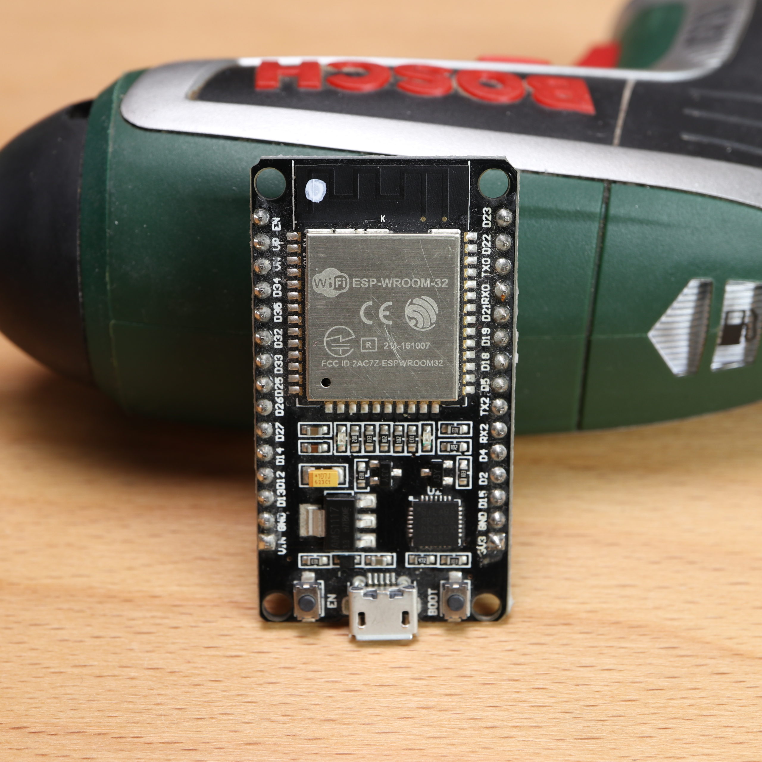
A hardware device that fulfills all these requirements are ESP32-based microcontrollers. Therefore, the retrofit will be applied with a ESP32 microcontroller (DEVKIT V1). The use of an ESP8266 should also be possible with the procedure shown in this tutorial.
Please note, that the idea of this tutorial is only to show how retrofitting of the IXO can be done. The goal is not, to have a fully working IoT device at the end. The tutorial will conclude with a list of open points that have to be addressed if the “IoT IXO” is meant for everyday use.
Hardware Retrofit
The first step is to open up the IXO. It is sufficient to remove only some part of the housing:
Just unscrew four screws and you will be able to remove the housing:

Now, you can see the inner parts. In order to make an “IoT IXO”, we need the Lithium-Ion rechargeable cell as power source for the ESP32. In order to grab the status of the IXO, we have two possibilities:
- The first option is to use the red push-button (running) and the red switch (direction).
- The second option is to use the electrical signal that lights up the LEDs on the top. If the IXO is running, the upper or lower LED is light up. Which LED is light up depends on the direction.
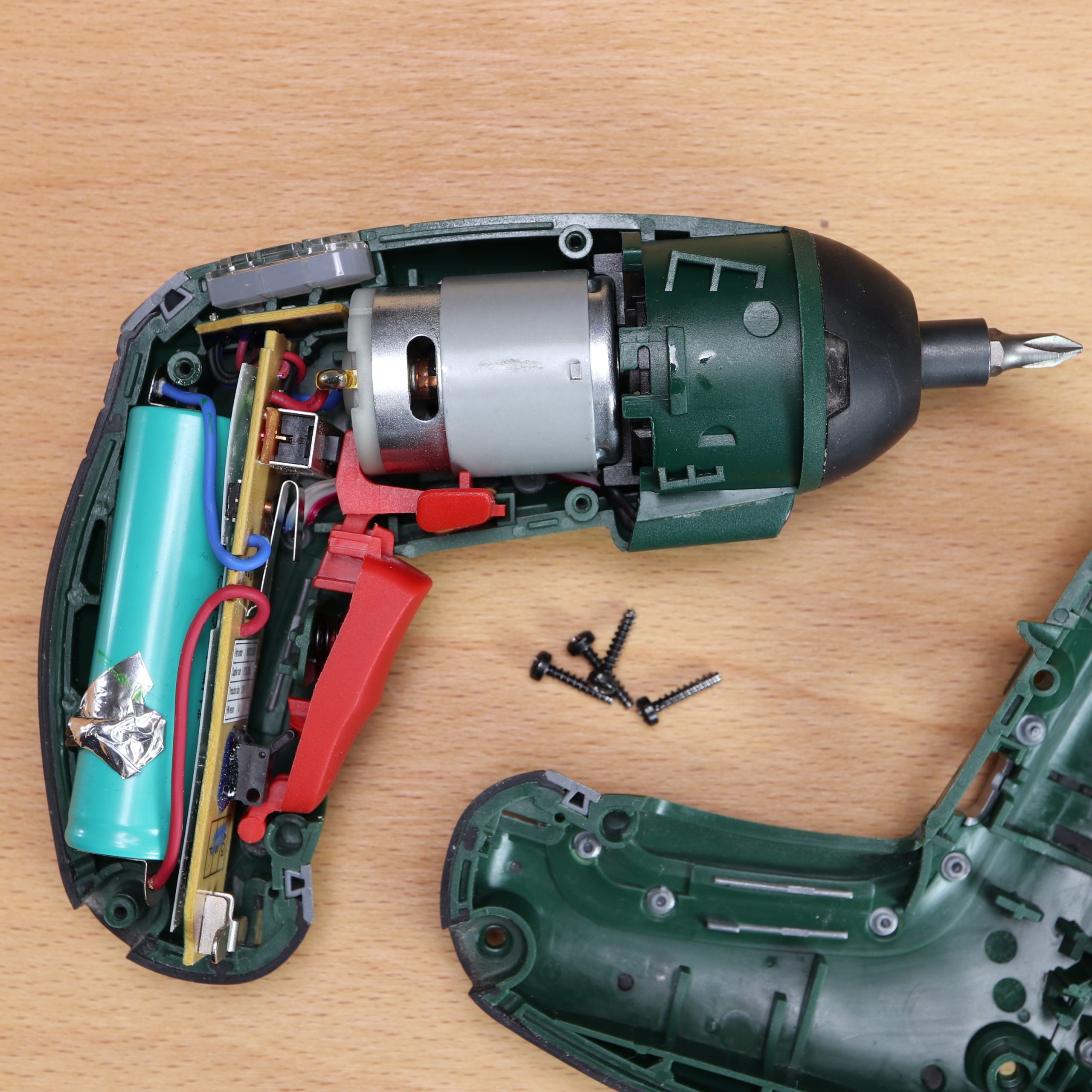
I decided to go for the second option and used the LED signal to retrieve the IXO’s state.
Wiring
Next, we have to wire the ESP32 to the IXO. As mentioned before, we make use of jumper wire clamps instead of a soldering station.
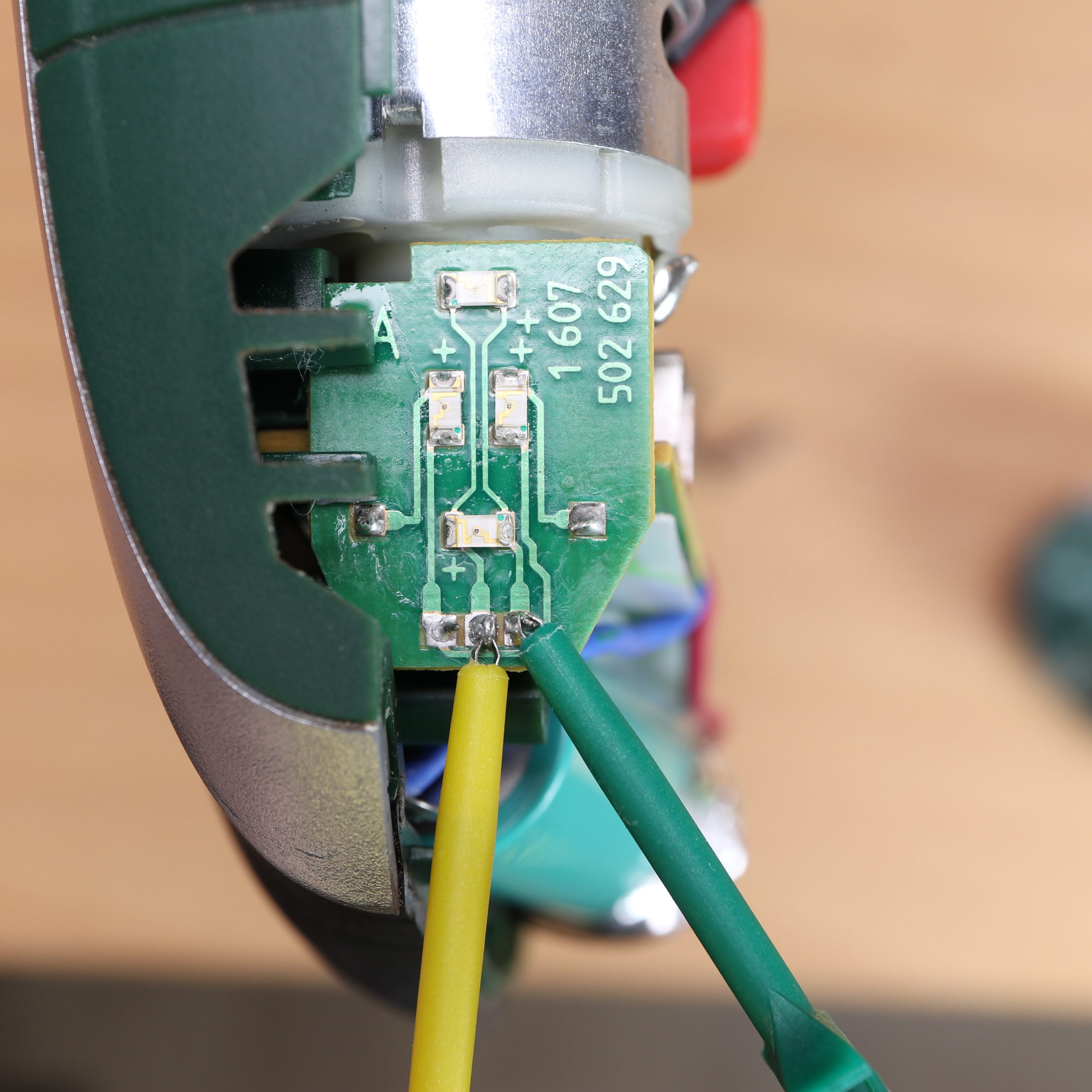
Let’s start with the wiring to detect the running and direction state. We have to wire the Arduino to the PCB that has the LEDs for the direction. The upper LED turns on if the IXO is running and in forward state. Accordingly, the lower LED turns on if the IXO is running and in reverse state. Interestingly, both LEDs share the same circuit paths. The upper LED’s anode is on the same path as the lower LED’s cathode. Likewise, The upper LED’s cathode is on the same path as the lower LED’s anode.
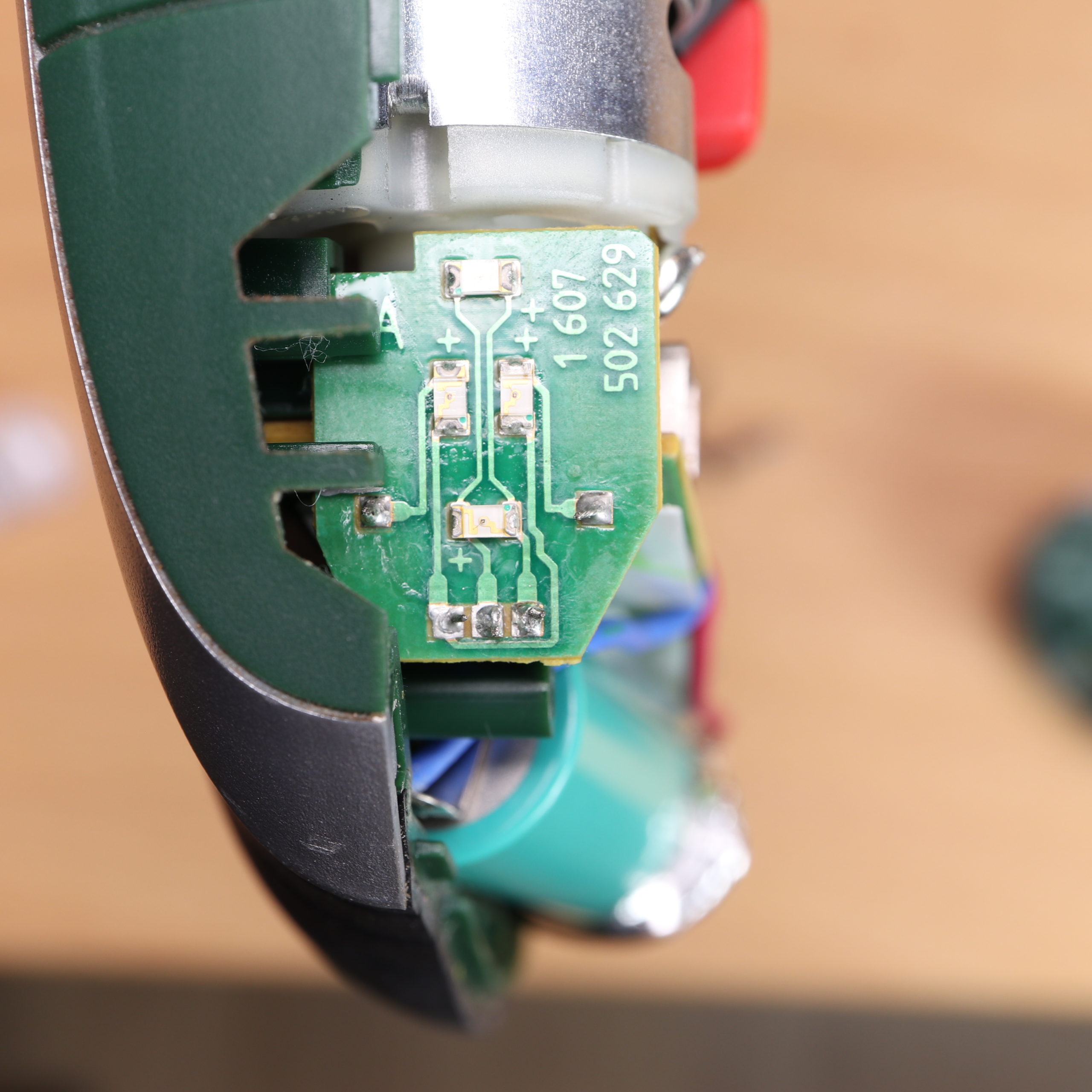
There are three pins at the bottom of the PCB. The middle pin and the right pin are relevant for our wiring:
- The middle pin is connected to the lower LED’s anode and upper LED’s cathode.
- The right pin is connected to the lower LED’s cathode and upper LED’s anode.
Here you see the resulting state table:
| Middle Pin (INPUT) | Right Pin (INPUT) | Lower LED (OUTPUT) | UPPER LED (OUTPUT) | State |
|---|---|---|---|---|
| 0 | 0 | 0 | 0 | IXO is not running |
| 0 | 1 | 0 | 1 | IXO is running / forward state |
| 1 | 0 | 1 | 0 | IXO is running / reverse state |
| 1 | 1 | 0 | 0 | IXO is not running / undefined state |
As a result, all we have to do is to wire the middle and right pin to GPIOs of our ESP32. We wire the right pin (FORWARD) to GPIO #2 and the middle pin (REVERSE) to GPIO #4. Alternatively, it would be possible to use other GPIO pins.
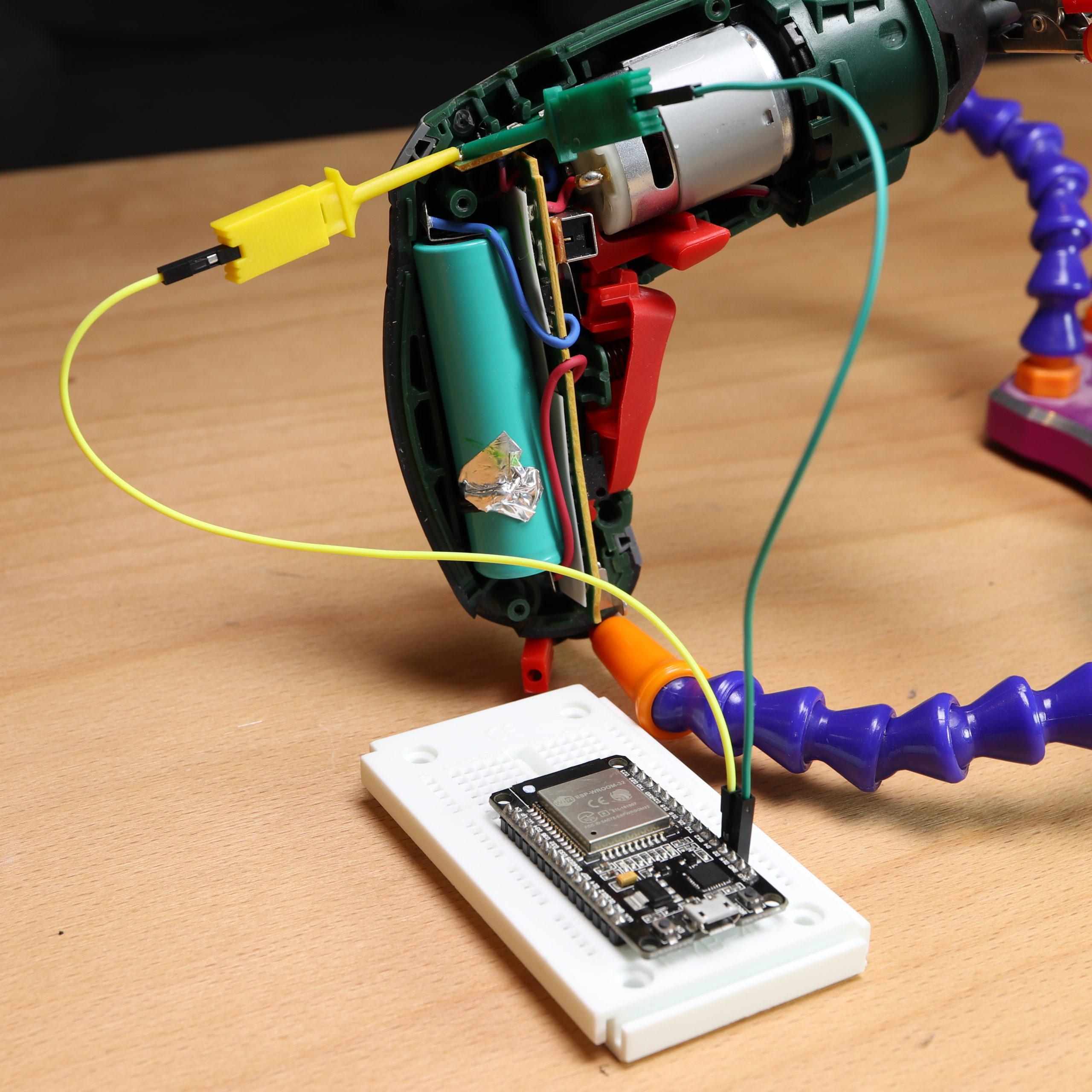
The wiring to supply (around) 3.3V to the ESP32 is very simple. Just wire the cell’s cathode (blue, negative) to GND and the anode (red, positive) to 3V3.
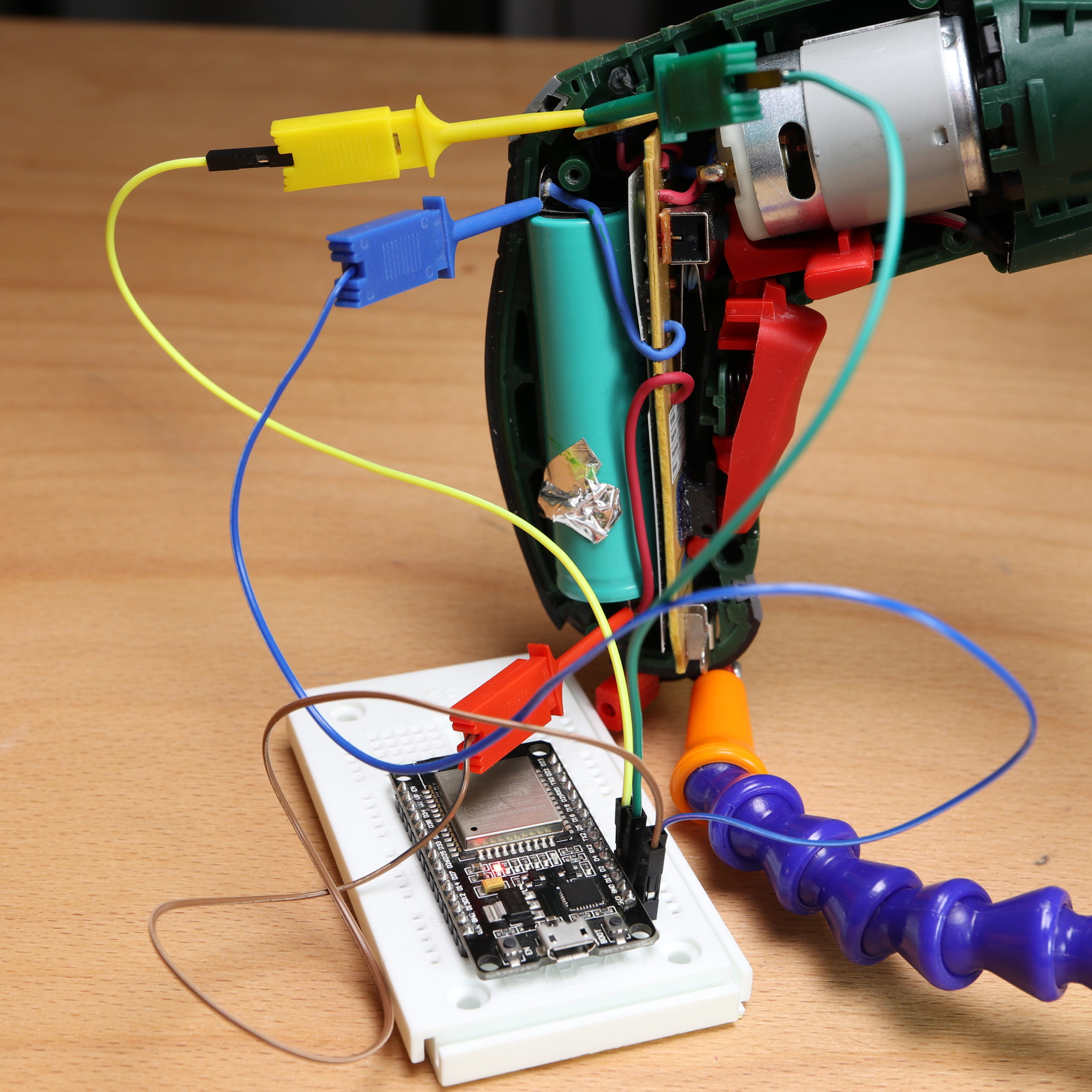
And that’s it for the wiring. Please be aware that the ESP32 is running all the time from now on. Moreover, if the clamps do not work for you, it might also be an option to solder wires from the GPIO pins to the PCB pins.
Programming
Next, the programming starts. The programming section is divided into two parts: First, we code a simple program to test whether we get the correct values. Second, we extend our program and add a webserver that enables us to monitor the running and direction states.
Simple IoT Retrofit (Test) Program
Ok, we start with programming the simple program. At the beginning of the program, the two pins (#2 and #4) are prepared. In the loop function, we read the forward and reverse states directly from the pins. The IXO is in running state, if either of them is true but not both (XOR). If the forward and reverse pin were both in high state, we set forward and reverse state to false. Then we print out the state values and wait for 500ms until the loop function is called again.
/*
MIT License
Copyright 2020 Michael Schoeffler (https://www.mschoeffler.de)
Permission is hereby granted, free of charge, to any person obtaining a copy of this software and associated documentation files (the "Software"), to deal in the Software without restriction, including without limitation the rights to use, copy, modify, merge, publish, distribute, sublicense, and/or sell copies of the Software, and to permit persons to whom the Software is furnished to do so, subject to the following conditions:
The above copyright notice and this permission notice shall be included in all copies or substantial portions of the Software.
THE SOFTWARE IS PROVIDED "AS IS", WITHOUT WARRANTY OF ANY KIND, EXPRESS OR IMPLIED, INCLUDING BUT NOT LIMITED TO THE WARRANTIES OF MERCHANTABILITY, FITNESS FOR A PARTICULAR PURPOSE AND NONINFRINGEMENT. IN NO EVENT SHALL THE AUTHORS OR COPYRIGHT HOLDERS BE LIABLE FOR ANY CLAIM, DAMAGES OR OTHER LIABILITY, WHETHER IN AN ACTION OF CONTRACT, TORT OR OTHERWISE, ARISING FROM, OUT OF OR IN CONNECTION WITH THE SOFTWARE OR THE USE OR OTHER DEALINGS IN THE SOFTWARE.

Explanation: Test application to check whether capturing of the running and direction state from a Bosch IXO screwdriver works.
*/

#define PIN_DIRECTION_FORWARD 2
#define PIN_DIRECTION_REVERSE 4

void setup() {

  Serial.begin(9600);

  pinMode(PIN_DIRECTION_FORWARD, INPUT);
  pinMode(PIN_DIRECTION_REVERSE, INPUT);

}

void loop() {
  bool state_direction_forward = digitalRead(PIN_DIRECTION_FORWARD);
  bool state_direction_reverse = digitalRead(PIN_DIRECTION_REVERSE);
  bool state_running = state_direction_forward ^ state_direction_reverse; // XOR (exclusive or) --> the IXO is running if either the forward or reverse state is active, but not if both states are active.

  if (state_direction_forward && state_direction_reverse) {
    // special case: both active means neither state is active (LED is not switched on)
    state_direction_forward = state_direction_reverse = false; // set forward and reverse to false
  }

  Serial.println("------------------------");
  Serial.print("State 'running': ");
  Serial.println(state_running);
  Serial.print("State 'forward': ");
  Serial.println(state_direction_forward);
  Serial.print("State 'backward': ");
  Serial.println(state_direction_reverse);
  Serial.println("------------------------");
  delay(500); // 500ms delay
}
IoT Retrofit Program with Webserver
Now, we extend our program program with a web server. The logic behind the web server is provided by the WebServer library.
In the setup function, we connect the ESP32 with a WiFi network. The SSID and password are hardcoded into the code (see open points). Moreover, all connection details (IP address) are printed out.
We use only basic functionality of the WebServer library in order to present a website to the user. There are two categories of provided URLs:
- REST URLs for the state values
- URL for the website
The four (REST) URLs to provide the ‘pure’ state values:
- /state_running (returns running state)
- /state_direction_forward (returns forward state)
- /state_direction_reverse (returns reverse state)
- /states (returns status of all three states)
The URL for the website is the root path “/”. The website is built up in the function “handleRoot”. In “handleRoot”, a very simple HTML document is created that uses only the “/states”-URL to retrieve the states each 500ms (by a JavaScript setInterval-function).
/*
MIT License
Copyright 2020 Michael Schoeffler (https://www.mschoeffler.de)
Permission is hereby granted, free of charge, to any person obtaining a copy of this software and associated documentation files (the "Software"), to deal in the Software without restriction, including without limitation the rights to use, copy, modify, merge, publish, distribute, sublicense, and/or sell copies of the Software, and to permit persons to whom the Software is furnished to do so, subject to the following conditions:
The above copyright notice and this permission notice shall be included in all copies or substantial portions of the Software.
THE SOFTWARE IS PROVIDED "AS IS", WITHOUT WARRANTY OF ANY KIND, EXPRESS OR IMPLIED, INCLUDING BUT NOT LIMITED TO THE WARRANTIES OF MERCHANTABILITY, FITNESS FOR A PARTICULAR PURPOSE AND NONINFRINGEMENT. IN NO EVENT SHALL THE AUTHORS OR COPYRIGHT HOLDERS BE LIABLE FOR ANY CLAIM, DAMAGES OR OTHER LIABILITY, WHETHER IN AN ACTION OF CONTRACT, TORT OR OTHERWISE, ARISING FROM, OUT OF OR IN CONNECTION WITH THE SOFTWARE OR THE USE OR OTHER DEALINGS IN THE SOFTWARE.

Explanation:
This program is part of an ESP32 tutorial that teaches how to retrofit a device for IoT applications.
The program reads some sensor values from a device and publishes them on a website.
*/

#include <WiFi.h>
#include <WiFiClient.h>
#include <WebServer.h>

const char* ssid = "YOUR SSID"; // add your WiFi SSID here
const char* password = "YOUR PASSWORD"; // add your password here
WebServer server(80);

#define PIN_DIRECTION_FORWARD 2
#define PIN_DIRECTION_REVERSE 4

bool state_direction_forward = false;
bool state_direction_reverse = false;
bool state_running = false;


void setup() {
  Serial.begin(9600);

  pinMode(PIN_DIRECTION_FORWARD, INPUT);
  pinMode(PIN_DIRECTION_REVERSE, INPUT);

  WiFi.mode(WIFI_STA);
  WiFi.begin(ssid, password);
  while (WiFi.status() != WL_CONNECTED) {
    delay(500);
    Serial.print("...trying to connect to WiFi.");
  }
  Serial.print("Connected to WiFi");
  Serial.print("SSID: ");
  Serial.println(ssid);
  Serial.print("IP address: ");
  Serial.println(WiFi.localIP());
  Serial.println("Initialized.");

  server.on("/", handleRoot); // callback function when user wants to access root path of domain

  server.on("/state_running", []() { // returns running-state as JSON object
    String str;
    str.concat("{ \"state_running\":");
    str.concat((state_running) ? "true" : "false");
    str.concat("}");
    server.send(200, "application/json", str);
  });

  server.on("/state_direction_forward", []() { // returns forward-state as JSON object
    String str;
    str.concat("{ \"state_direction_forward\":");
    str.concat((state_direction_forward) ? "true" : "false");
    str.concat("}");
    server.send(200, "application/json", str);
  });

  server.on("/state_direction_reverse", []() { // returns reverse-state as JSON object
    String str;
    str.concat("{ \"state_direction_reverse\":");
    str.concat((state_direction_reverse) ? "true" : "false");
    str.concat("}");
    server.send(200, "application/json", str);
  });

  server.on("/states", []() { // returns all states as JSON object
    String str;
    str.concat("{ ");
    str.concat("\"state_running\":");
    str.concat((state_running) ? "true" : "false");
    str.concat(",");
    str.concat("\"state_direction_forward\":");
    str.concat((state_direction_forward) ? "true" : "false");
    str.concat(",");
    str.concat("\"state_direction_reverse\":");
    str.concat((state_direction_reverse) ? "true" : "false");
    str.concat("}");
    server.send(200, "application/json", str);
  });

  server.begin();
  Serial.println("HTTP server started");
}

void loop() {
  server.handleClient();

  state_direction_forward = digitalRead(PIN_DIRECTION_FORWARD);
  state_direction_reverse = digitalRead(PIN_DIRECTION_REVERSE);
  state_running = (state_direction_forward != state_direction_reverse); // XOR (exclusive or) --> the nexo is running if either the forward or reverse state is active, but not if both are active.

  if (state_direction_forward && state_direction_reverse) {
    // special case: both active means neither state is active (LED is not switched on)
    state_direction_forward = state_direction_reverse = false; // set forward and reverse to false
  }

  Serial.println("------------------------");
  Serial.print("IP address: ");
  Serial.println(WiFi.localIP());
  Serial.print("State 'running': ");
  Serial.println(state_running);
  Serial.print("State 'forward': ");
  Serial.println(state_direction_forward);
  Serial.print("State 'backward': ");
  Serial.println(state_direction_reverse);
  Serial.println("------------------------");
}

// If the root path is called a very basic website is shown. The website shows the current state values.
// The state values are updated each 500ms.
void handleRoot() {
  server.send(200, "text/html", " \
    <!DOCTYPE html> \
    <html> \
    <head><title>Retrofit IoT Example</title><meta charset='UTF-8'></head> \
    <body> \
    <label for='state_running'>State running</label><input id='state_running'><br> \
    <label for='state_direction_forward'>State direction forward</label><input id='state_direction_forward'><br> \
    <label for='state_direction_reverse'>State direction reverse</label><input id='state_direction_reverse'><br> \
    </body> \
    <script> \
    setInterval(function() { \
      var xmlhttp = new XMLHttpRequest(); \
      var url = '/states'; \
      xmlhttp.open('GET', url); \
      xmlhttp.onreadystatechange = function() { \
        if (xmlhttp.readyState == 4 && xmlhttp.status == 200) { \
            var obj = JSON.parse(xmlhttp.responseText); \
            document.getElementById('state_running').value = obj.state_running; \
            document.getElementById('state_direction_forward').value = obj.state_direction_forward; \
            document.getElementById('state_direction_reverse').value = obj.state_direction_reverse; \
        } \
      }; \
      xmlhttp.send(); \
    }, 500);\
    </script> \
    </html> \
    ");
}
Try out the IoT Retrofit Application!
If the ESP32 is correctly programmed and wired to the IXO, you should be able to visit the ESP32’s website. Just enter the ESP32’s IP address into your browser and you should see the website. You can find out the IP by having a look at your WiFis router administration view. Alternatively, you can read the serial messages of the ESP32 (ESP32 must still be connected to your PC). If the website is shown, just change the state on your IXO and you should see the corresponding state values on the website.
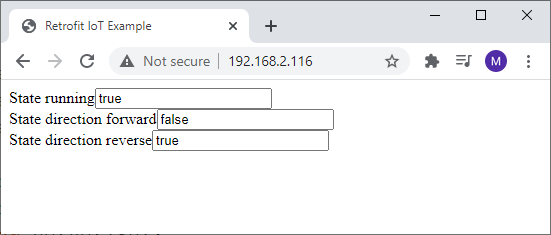
Here I go into reverse state and start screwing:
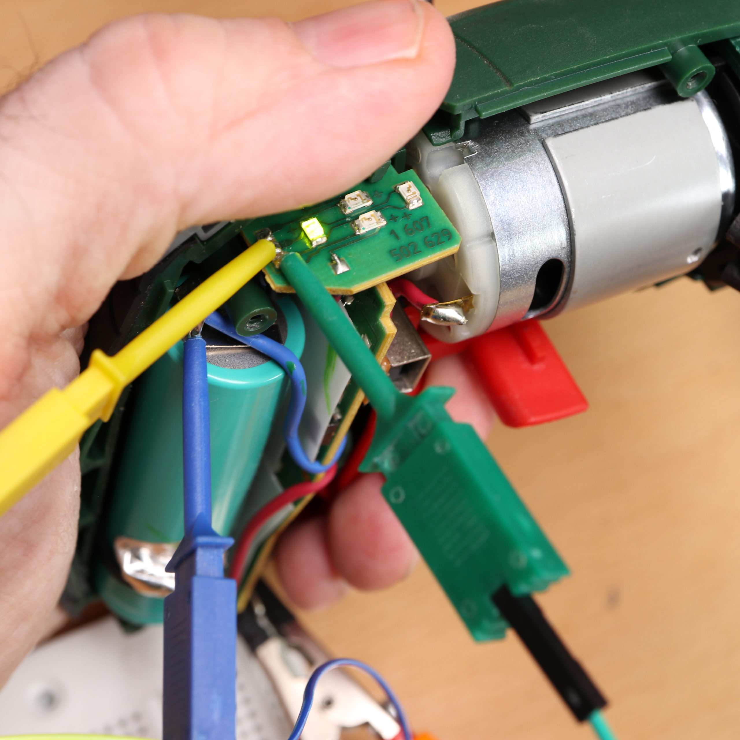
At the same time, the website shows that the IXO is running and in reverse state:
And that’s how you perform an IoT retrofit on an old IXO screwdriver!
Open Points
As mentioned before, the “IoT IXO” is not meant for everyday use. In fact, it still has an open housing and can’t be used at all. Nonetheless, the “IoT IXO” has been a good subject on showing how retrofitting can be achieved. These points have to be addressed, if you plan to actually use the IoT IXO:
- Find a use case that justifies the “IoT features”: If you do not have any reason to use the new IoT features, the device will be put aside after some time. A lot of devices are enhanced by “IoT features” (washing machines, fridges, etc.). However, if someone does not see any increased value, the IoT features become only additional complexity without any purpose.
- Power control for ESP32: The ESP32 devkit is directly wired to the IXO’s power source, i.e. the ESP32 is always on — even if the IXO is not in use. You might want to have a switch or something else, to be able to turn it on and turn it off.
- Improved wiring: I used some jumper wire hooks/clamps to wire the IXO to the ESP32 devkit. Naturally, this will not hold for very long if the screwdriver is in actual use. Therefore, the wiring must be improved (e.g. by soldering the wires).
- New housing: The ESP32 devkit does not fit into the housing of the IXO. To have an open housing while using the IXO is not an option. Therefore, you might want to make a new housing shell (e.g. with the help of an 3D printer).
- Network Connectivity: The current version has a “hardcoded” WiFi password. If the IXO should be able to connect to another WLAN, a different authentication method is required.
Summary
We made use of an ESP32 devkit to “IoT retrofit” an Bosch IXO screwdriver. Although the IXO is still missing some modifications for everyday use, we are able to connect to the screwdriver an monitor its states. The ESP32 devkit turned out as perfect retrofit hardware, especially since it has the same operating voltage as the IXO.
Video Tutorial