This tutorial shows how to control so-called “fairy LED strings” (also called LED strings, fairy lights, fairy LEDs etc.) with an Arduino. The idea is to have multiple fairy LED strings that are switched on and off corresponding to a specific pattern. Typically, these strings are either powered with a battery pack or with a USB cable/power supply. Here, we focus on the USB-powered LEDs, since they are easier to get working with an Arduino. Arduinos are normally not able to provide enough power for such fairy stringy by their digital outputs. Therefore, we make also use of a relay modules in this tutorial.
List of materials:
Components

Fairy LED Strings
I don’t know for sure, but fairy LED strings are maybe called fairy LEDs strings, as they look like tiny fairies when watching from some distance. In many stores, they are presented inside a jar which might remind on the fairies of the popular video game series “Zelda” (where fairies are often transported in jars by the main protagonist “Link”).
Normally, fairy LED strings consist of a chain of simple LEDs which are connected via insulated copper wire. In order to make the LEDs more robust, they are wrapped in some sort of dry hot glue.
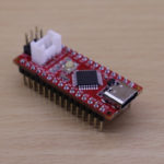
Arduino (Seeeduino Nano)
In this tutorial, I make use of a Seeeduino Nano from Seeedstudio which comes with a nicely red-colored PCB. Additionally, it’s compatible to a conventional Arduino Nano. In contrast to a normal Arduino Nano, it has a USB Type-C connector instead of a USB Mini connector. This might be an advantage if you own more USB Type-C cables than USB Mini cables (imho which are rarely distributed nowadays). In this tutorial, the Seeedunio Nano is used to “store the lightning program” and control the fairy LEDs strings according to this program.
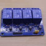
Relay module
In order to switch on an LED, the Seeeduino must bring 5V to the fairy LED string’s USB connector. To my knowledge, typical Arduinos are only able to provide 40mA via an digital output pin. Normally, this is not sufficient to power a string with multiple LEDs. In order to account for this, we utilize a relay module. A relay module (as used in this tutorial) exists in different variants: supporting 1-, 2-, 4-, 8 ports. In this tutorial, the HL-545 with 4 ports is used to power two fairy LED strings (yellow and blue).
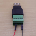
USB Terminal Adapter
Now, the question is how to wire a USB-based fairy LED string to a breadboard / “jumper wire system”. For this use case, a female USB terminal adapter is quite useful. These adapters allow you to plug in an USB cable and, then, have the corresponding signal also on a terminal block. Luckily, jumper wires can be easily connected to the terminal blocks. In particular, we are interested to connect the GND/- and 5V/+ pins of the USB cable to two separate jumper wires.
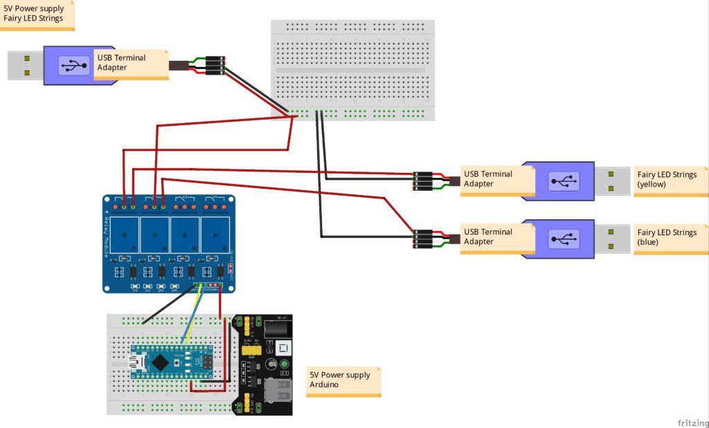
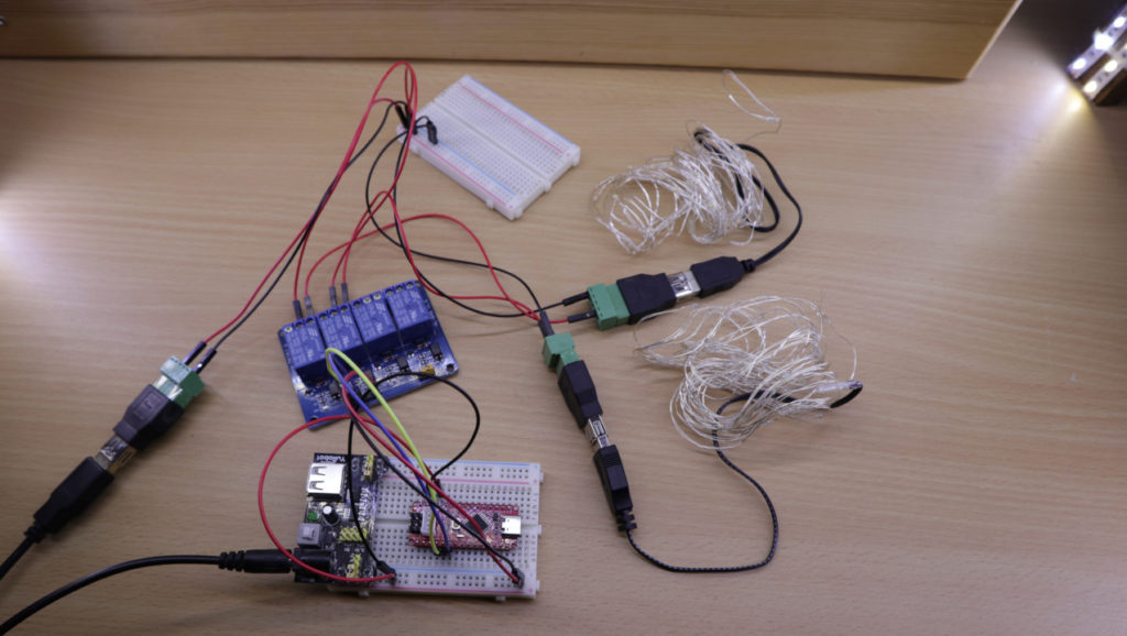
Wiring
In this setup exist two 5V circuits. The first one is for powering the fairy LED strings. The second one is for powering the Arduino and the relay module. It would also be possible to have only one 5V circuit which powers all components.
Source code
The program is very basic since there is no special code for the relay module or for the fairy LED strings… it is more or less only setting two output pins. The idea of the program is to perform a little “light show”. In the first phase, no fairy LED strings is on. Then, only the yellow string is shown. Next, only the blue string is shown. Finally, both strings are shown. In addition, each phase is shown for two seconds.
In the setup function, digital pin 2 and 3 are declared as output pins. Then in the loop function, the “light show phases” are represented by setting the two outputs pin and adding a delay of two seconds. For example, if both LEDs are set, the output pins are set two LOW. Yes, LOW is correct as the relay model triggers on LOW signals!
// (c) Michael Schoeffler 2019, http://www.mschoeffler.de
// This program shows how to switch on two different "fairy LEDs" by utilizing a relay module.
// In particular, the program resembles a small "lighting program":
// Both LEDs are off, only first LED is switched on, only the second LED is switched on, both LEDs are switched on.
// Each "light mode" shows up for two seconds.

void setup() {
  pinMode(2, OUTPUT); // Digital pin 2 is an output pin
  pinMode(3, OUTPUT); // Digital pin 3 is an output pin
}

void loop() {
  // keep in mind: relay module "switches on" if signal is LOW

  // nothing is switched on
  digitalWrite(2, HIGH);
  digitalWrite(3, HIGH);

  delay(2000); // wait for two seconds.

  // LED is switched on
  digitalWrite(2, LOW); //Fairy LED on digital output 2 is switched on
  digitalWrite(3, HIGH);

  delay(2000); // wait for two seconds.

  // the other LED is switched on
  digitalWrite(2, HIGH);
  digitalWrite(3, LOW); //Fairy LED on digital output 3 is switched on

  delay(2000); // wait for two seconds.

  // both LEDs are switched on
  digitalWrite(2, LOW);  //Fairy LED on digital output 2 is switched on
  digitalWrite(3, LOW); //Fairy LED on digital output 3 is switched on

  delay(2000); // wait for two seconds.


}
If the program is transferred to the Seeeduino Nano/Arduino, the “lighting show” should look like this:

Video tutorial